1.Application products
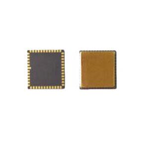
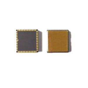
North seeking MEMS Gyro ER-MG2-50/100
Navigation grade MEMS Gyro ER-MG2-300/400
Tactic grade MEMS Gyro ER-MG-067
2.Schematic diagram designing

FIG. 5 Refer to schematic diagram
3.PCB design
The decoupling capacitors of pin VCP, VREF, VBUF and VREG should be placed as close as possible to the pin and the equivalent resistance of the routing should be reduced as much as possible.
The other end of the decoupling capacitor of VREF, VBUF and VREG is connected to AVSS_LN nearby, and then connected to the signal ground through magnetic beads.
The VCC and VIO decoupling capacitors are also placed close to the corresponding pins. When VCC is working normally, the overall current will be about 35mA, so wide PCB needs to be used for wiring to ensure voltage stability.
In order to make the device assembly smooth, avoid wiring under the package as far as possible.
Position devices as far as possible away from stress concentration areas. Avoid large heat dissipation elements and areas with extruded and pulled external mechanical contact, as well as areas such as positioning screws that are prone to warping during integral installation.
More Technical Questions
1.The Calibration Method of High Precision MEMS Gyro
2.Feasibility Analysis of MEMS Gyro North Seeking
3.What is the Hardware Interface of Ericco MEMS Gyro
4.How to Distinguish MEMS Accelerometer and MEMS Gyroscope Correctly?
5.ER-MG2-100 (0.02°/h) High Precision MEMS Gyroscope
6.Analysis of the main performance parameters of MEMS gyroscope
Products in Article