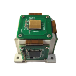
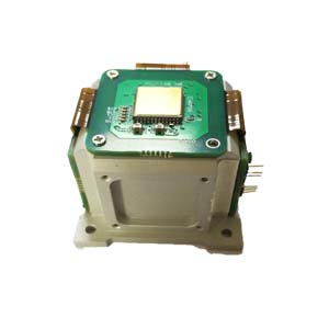
1.Application products:
North seeking MEMS Gyro ER-MG2-100
Navigation grade MEMS Gyro ER-MG2-300/400
Tactic grade MEMS Gyro ER-MG-067
2.Package Information
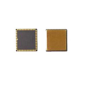
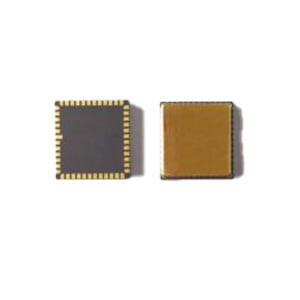
2.1 Adopt 48 pin ceramic package

Figure 1 encapsulates the diagram

Figure 2 Package size diagram
2.3 Axis of rotation

Fig.3 Axial diagram of rotation detection
The MEMS gyro is a single-axis high performance gyroscope that detects the rotary axis perpendicular to the chip surface.
Counterclockwise rotation along the axis of rotation is positive and clockwise rotation along the axis of rotation is negative.
2.3 Pin definition

Figure 4 Pin definition
| NO | Pin Names | Electrical properties | Nominal Voltage | Description |
| 1 | GND | GND | 0V | / |
| 2 | VCC | Power Input | 5V | Supply voltage input, 10uF, 0.1UF bypass capacitance to the ground. |
| 3 | VIO | Interface Voltage | 1.6V~5V | The input voltage will be used as the reference voltage of the interface and shall be consistent with the interface voltage of the controller. A 0.1UF bypass capacitor is required to the ground |
| 4 | GND | GND | 0V | / |
| 7 | EN | Input | VIO | Chip enablement. Input high enabling chip. |
| 8 | CSS | Input | VIO | SPI chip selection |
| 9 | SI | Input | VIO | SPI data input |
| 10 | SCLK | Input | VIO | SPI clock input |
| 11 | SO | Output | VIO | SPI data output |
| 18 | GND | GND | 0V | / |
| 19 | GND | GND | 0V | / |
| 30 | GND | GND | 0V | / |
| 34 | GND | GND | 0V | / |
| 37 | GND | GND | 0V | / |
| 38 | VREG | Reference Voltage | 4V~6V | Internal voltage reference, connect 1uF bypass capacitor to ground |
| 39 | VBUF | Reference Voltage | 1.65V | Internal voltage reference, connect 1uF bypass capacitor to ground |
| 40 | VREF | Reference Voltage | 2.4V | Internal voltage reference, connect 1uF and 0.01uF bypass capacitors to the ground |
| 41 | VCP | Reference Voltage | 11V | Internal voltage reference, connect 1uF (withstand voltage greater than 16V) bypass capacitance to the ground |
| 42 | GND | GND | 0V | / |
| 43 | VCC | power input | 5V | Supply voltage input, 10uF, 0.1UF bypass capacitance to the ground. |
| 44 | GND | GND | 0V | / |
| 47 | SYNC | Input | VIO | Sampling synchronous signal input, can be suspended when not in use. |
| 48 | INT | Output | VIO | Interrupt signal output, can be suspended when not in use. |
| Remark: The rest of the NC pins, suspended, not connected. |
||||
Table 1 Pin definition and description
More Technical Questions
1.The Calibration Method of High Precision MEMS Gyro
2.MEMS gyroscope VS FOG: What’s the difference between them?
3.Feasibility Analysis of MEMS Gyro North Seeking
4.How to Distinguish MEMS Accelerometer and MEMS Gyroscope Correctly?
5.ER-MG2-100 (0.02°/h) High Precision MEMS Gyroscope
6.Analysis of the main performance parameters of MEMS gyroscope
Products in Article