Electronic compass can greatly reduce the interference of the surrounding inherent magnetic field through calibration, and accurately indicate the azimuth Angle, but it is helpless to change the magnetic field interference. During the use of the electronic compass, the proximity of iron and magnetic substances will be avoided as far as possible. However, some electronic compass platforms have variable magnetic field interference from inside the platform, which moves with digital compass. This kind of interference source has the characteristics of fixed relative position and changing magnetic field.
At this time, there are three common technical ways: ① let the changing magnetic field temporarily stop changing or use magnetic shielding materials to isolate interference; ② Find a new way to use dual GPS, AHRS and other systems to indicate the azimuth Angle to avoid the interference of variable magnetic field; ③ The influence of the variable magnetic field interference source on the surrounding magnetic field is measured, and then the azimuth of digital compass is compensated according to the change of the magnetic field. In some use cases, it is not possible to shield the variable magnetic field interference, and due to the limitations of the loading platform, it is not possible to use the dual GPS and AHRS systems that are expensive, heavy and require large space. At this point, the third technical approach becomes the only viable solution.
1.Variable magnetic field interferes with important laws
The magnetic steel and digital compass are fixed in the corresponding position of the test tool, and the reluctance sensor and the Hall sensor with large range are selected for testing respectively. The magnetic sensor is placed in different positions on the tooling, and the readings of the electronic compass and magnetic sensor without magnetic steel and under different magnetic steel attitudes are recorded respectively when the tooling is in different orientations for collation and comparison. It is assumed that G magnetic steel is the change in the reading of a certain axis of the magnetic sensor caused by the change in the attitude of the magnetic steel, that is, the reading of the magnetic sensor when the magnetic steel is present minus the reading of the magnetic steel when the magnetic steel is not present, which represents the influence of the magnetic steel on the magnetic field where the magnetic sensor is located. Through a large number of experiments and summary, it is found that in a certain area, when the magnetic sensor is arranged along the virtual magnetic field line formed by the magnetic steel, there are the following important laws:
(1) Gmagnetic steel rapidly decreases with the increase of distance. For example, at 1cm away from the magnetic steel, G magnetic steel is about ±200000, at 10cm is ±1500, at 20cm is ±200, at 30cm is ±65, at 40cm is ±30. The magnetic readings at the test site were slightly less than ±300.
(2) When the test tool is facing different directions, the G magnetic steel is a fixed value. Figure 1 shows the change rule of G magnetic steel at a distance of 10cm from the magnetic steel, and the horizontal axis shows the orientation of N grade magnetic steel, which is divided into 8 directions. You can see that the four directions of the curve basically coincide. The other two axes of the magnetic sensor also fully conform to this law.
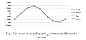
When the magnetic steel is in the same attitude, the direction of the magnetic field influence value along the direction of the virtual magnetic induction line formed by the magnetic steel is the same, and the value is proportional to the relationship, that is:
![]()
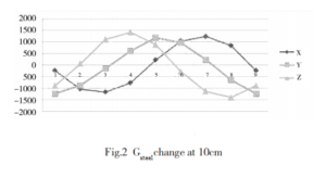
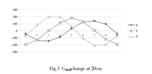
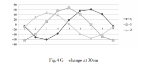
Where, G magnetic steel A and G magnetic steel B are two different positions on the virtual magnetic induction line formed by magnetic steel, and the magnetic field change vector caused by the change of magnetic steel attitude. Figure 2~5 shows the change curve of G magnetic steel at 10cm, 20cm and 30cm caused by magnetic steel rotation when the tool is facing north. The horizontal axis is the different posture of the magnetic steel, and the 3 curves represent the x, y and z axes respectively. In the preliminary test, the magnetic sensor was placed manually, and the position error was too large. In subsequent experiments, with the improvement of the accuracy of the magnetic sensor position and navigation attitude, the curve consistency became more obvious, and the law was repeatedly verified.
2.Dual magnetic sensor compensation
According to the above three rules, without considering the interference of other parts of the platform, a test and compensation method based on double magnetic sensors is proposed, which can effectively measure the influence of the attitude change of the magnetic steel on the magnetic field at the position of digital compass. Place A magnetic sensor numbered B near the flux gate of the digital compass (electronic compass three-axis magnetic sensor reading can also be used, that is, digital compass as A magnetic sensor B), and another magnetic sensor numbered A is placed in accordance with the above relationship and easy to install on the platform, keeping the A and B magnetic sensors and digital compass three axes in the same direction. Suppose the output of a magnetic sensor axis in the experiment is
G = Gground+Gmagnetic steel+ Ginterference
Gground and Ginterference are geomagnetic components and environmental interference components of this axis, respectively. Due to the close distance between the two magnetic sensors, in the case of away from external strong magnetic interference can be obtained:
Ginterference A≈Ginterference B,Gground A=Gground B
Where, GA and GB are the readings of the same axis on the magnetic sensor A and B. When the position of A and B magnetic sensors is fixed, the ratio k of their change quantity can be obtained at a constant value. Therefore, the influence component caused by the attitude change of the magnetic steel at the magnetic sensor B, that is, at electronic compass, can be easily obtained according to the above formula.
The above experimental findings and reasoning provide a new way of thinking, using two small and cheap magnetic sensors to calculate the magnetic field changes near digital compass caused by the attitude changes of the magnetic steel in an unusually simple way. Then it is only necessary to study the relationship between this variation and the azimuth offset of digital compass. It is not necessary to calculate the attitude of the magnetic steel according to the change of the magnetic field near the magnetic steel, nor is it necessary to study the complex mapping relationship between the magnetic steel attitude and the azimuth offset of digital compass when the platform is in different azimuth angles, pitch angles and roll angles, which greatly simplifies the calculation process. The data collection workload is greatly reduced.
Summary
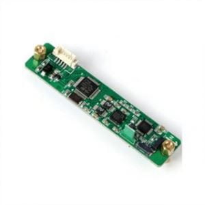
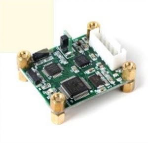
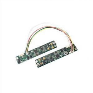
In this paper, the calibration and compensation method of dual magnetic sensor based on the proportional relation of specific position is proposed for the fixed variable magnetic field interference source. This method has many advantages such as simple acquisition operation, low cost, convenient use and high fault tolerance. It provides a new idea for calibration compensation of variable field interference sources. For digital compasses, we currently have a wide range, such as the digital output full attitude 3D digital compass ER-EC-360A, the high-precision electronic compass ER-EC-225CAN, and the low-cost electronic compass ER-EC-225.
More Technical Questions
1.Electronic compass dynamic heading error correction
2.Soft Magnetic Error Compensation Method of Electronic Compass
3.Electronic Compass Hard Magnetic Error Compensation
4.Application of Gyroscope in Electronic Compass
5.Principle of digital compass
6.What Is The Difference Between Gyro Error and Compass Error in Navigation?
Products in Article