The working principle of the gyroscope is based on its north-seeking characteristics, and the north-seeking methods are based on its north-seeking characteristics. Rigid rotor gyroscopes are currently the most widely used gyroscopes. The core part of this gyroscope is a rigid rotor that rotates around the gyroscope axis at high speed. The rotor of a gyroscope is usually driven by a gyro motor, causing it to rotate around the gyro axis at high speeds, up to several thousand to tens of thousands of revolutions per minute. The main working principle of a gyroscope is based on the two basic characteristics of the gyroscope itself: axis fixation and precession. When there is no external force acting on a uniformly rotating gyroscope, that is, when the external torque is zero, it strives to maintain its own rotational inertia and make its axis of rotation point to the inertial space (datum space, a star far away from the earth in this space). It seems that they are stationary, or it takes a long time to measure their motion. Newton's laws of motion apply to this space.) The constant initial direction is the fixed axis of the gyro, that is, its stability; when the gyro is acted upon by an external torque When , the spin axis of the gyro moves in the direction of the external torque. This is the precession of the gyro: when the gyro axis is acted upon by an external force, it precesses in the direction of the external torque at a minimum angle.
1.Orientation method of gyro-theodolite
1.1 Orientation field process of gyro-theodolite
(1) Measure the instrument constants on the known edge of the ground

Figure 1 Schematic diagram of gyroscope orientation
The gyroscope axis, the optical axis of the telescope and the optical axis represented by the zero line of the observation eyepiece reticle are usually not in the same vertical plane, and the stable position of the imaginary gyroscope axis usually does not coincide with the geographical meridian. The angle between the two is called the instrument constant, generally represented by Δ. If the gyroscope meridian is east of the geographical meridian, Δ is positive; otherwise, it is negative. The instrument constant Δ can be measured directly on the edge of a precision wire with a known azimuth angle.
(2) Measure the gyro azimuth angle on the underground orientation edge
The length of the underground directional edge should be greater than 50m. The instrument is placed at point C′, as shown in Figure 1. The gyro azimuth angle aT of the C′D′ edge can be measured, and the geographical azimuth angle A of the directional edge is . Measuring the azimuth angle of the directional edge gyro should be carried out twice independently, and the mutual difference should be less than 40″ for GAK-1, JT15 and other models of instruments.
(3) Re-measure the instrument constants after the instrument is installed in the well.
After the instrument is installed in the well, the instrument constants should be re-measured 2 to 3 times on the known edge. For the instrument constants measured twice before and after, the difference between any two instrument constants should be less than 40" for GAK-1 and JT15 instruments. Then find the best value of the instrument constants, and evaluate it according to Bessel's formula Error in measurement.
(4) Calculate the meridian convergence angle
Generally, the coordinate azimuth angle α0 of the precision wire edge or triangulation network edge on the ground is known. The underground directional edge that needs to be calculated also requires its coordinate azimuth angle α, not the geographical azimuth angle A. Therefore, it is also necessary to calculate the meridian convergence angle γ. The relationship between geographical azimuth and coordinate azimuth is:![]() The sign of the meridian convergence angle γ0 can be determined
The sign of the meridian convergence angle γ0 can be determined
by the location of the instrument point, that is, it is positive to the east of the central meridian and negative to the west; its value can be obtained based on the Gaussian plane coordinates of the instrument point.
(5)Calculate the coordinate azimuth of the underground directional edge
From Figure 1 and the above formula, we can get:![]() The coordinate azimuth angle of the underground directional edge is:
The coordinate azimuth angle of the underground directional edge is:![]()
In the formula: ——The average value of instrument constants:![]()
2.Gyroscope sling zero position observation
The zero position of the suspension belt refers to the equilibrium position of the torsion caused by the torsion of the suspension belt and the guide wire when the gyro motor is not rotating, which is the position where the torsion torque is zero. This position should be on the zero reticle of the eyepiece reticle. Before and after the gyroscope observation work starts and ends, the zero-position observation of the sling must be carried out, which is called the pre-measurement zero-position observation and the post-measurement zero-position observation. When measuring the suspension zero position, first level the theodolite and fix the sighting part, lower the gyro sensitive part and observe the swing of the sensitive part in the reading mirror. Read three reversal points continuously on the reticle and estimate to 0.1 division. The observation process is shown in Figure 2. zero position
![]() ; At the same time, a stopwatch is needed to measure the period, that is, the time it takes for the cursor image to swing through the zero line of the reticle for one week, and its reading is called the free swing period. After the zero position observation is completed, lock the sensitive part.
; At the same time, a stopwatch is needed to measure the period, that is, the time it takes for the cursor image to swing through the zero line of the reticle for one week, and its reading is called the free swing period. After the zero position observation is completed, lock the sensitive part.

Figure 2 Zero observation
3.Rough orientation
Before determining the gyro azimuth of a known side and an orientation side, the collimation axis of the theodolite telescope must be placed approximately north and roughly oriented. Compass rough orientation. Use the coordinate azimuth of the known side to directly find approximate north. Two reversal point method. When the reversal point is reached, calculate the approximate reading of north on a horizontal dial:![]() Rotate the collimation part, place the telescope at the N′ reading position, and add the instrument constant, then the collimation axis points to approximately north.
Rotate the collimation part, place the telescope at the N′ reading position, and add the instrument constant, then the collimation axis points to approximately north.
4.Precision orientation
Precision orientation is the precise determination of the gyro azimuth angle of a known side and an orientation side. The main method is that the sighting part of the instrument is in a tracking state, which is the reversal point method that has been used at home and abroad for many years. When observing using the reversal point method, the operating procedures of the gyro-theodolite at a survey station are as follows:
(1) Strictly arrange the theodolite, set up the gyroscope, measure the direction value of the undetermined or known survey line in one measurement round, and then align the instrument roughly to the north.
(2) Lock the swing system, start the gyro motor, and after reaching the rated speed, lower the gyro sensitive part for rough orientation. Brake the gyro and hold it up and lock it, turn the telescope's collimation axis to an approximate north position, and fix the collimation part. Adjust the horizontal micro-screw to the middle position of the stroke range.
(3) Turn on the gyro lighting, lower the sensitive part of the gyro, observe the zero position of the sling before testing, and use a stopwatch to record the self-swing period T3. After the zero position observation is completed, lift and lock the sensitive part.
(4)Start the gyro motor, and after reaching the rated speed, slowly lower the sensitive part to the semi-detached position, pause for a few seconds, and then lower it completely. If the cursor image moves too fast, use semi-detachment damping limiter to keep the swing amplitude in the range of about 1° to 3°. Use the horizontal micro-movement screw to micro-move the sighting part so that the cursor image coincides with the zero reticle line of the reticle at any time, that is, tracking. The tracking should be smooth and continuous, and avoid not tracking in a timely manner, such as sometimes lagging behind the swing of the sensitive part, and sometimes quickly catching up or being much ahead. These situations will affect the accuracy of the results. When the swing reaches the reversal point, read 5 reversal point readings continuously. Then lock the sensitive part and brake the gyro motor. When tracking, you also need to use a stopwatch to measure the tracking swing period T1. The average reading NT of the swing balance position on the horizontal dial is called the gyro north direction value, and is calculated using the following formula:

The difference between the median swing values of the gyroscopes should not exceed 25″ for JT15 and GAK-1 instruments.
(4) Zero position observation after the test, the method is the same as the zero position observation before the test.
(5) Determine the direction value of the undetermined or known survey line in one measurement round. The difference between the two observation results before and after the test shall not exceed 10″ and 25″ respectively for J2 and J6 class theodolite. Take the average value of the two measurement rounds before and after the measurement as the measurement line direction value.
5.Contact measurement when the vertical shaft is oriented using a gyro-theodolite
The contact measurement when orienting through a shaft using a gyro-theodolite consists of three parts:
①Injection point; ②Measurement of the upper, lower and connection points of the well; ③Gyro-theodolite orientation of the starting edge of the well.
(1) Throwing point: laser vertical point throwing instrument steel wire throwing method.
(2) Connection: ground connection; underground connection;
(3) Orientation: Carry out gyro-theodolite orientation on the selected starting edge and obtain the coordinate azimuth angle α0 of the edge.
(4)In-house calculations
①According to the ground connection measurement results, calculate the vertical
The coordinates of ball line A.
② Calculate the coordinate azimuth angles of each side of the underground connecting wire.
③ Calculate the coordinates of the starting point of the underground wire.
6.Precautions when orienting the gyro-theodolite
(1) The instrument must be used by personnel with certain operating experience. Measuring the instrument constants twice before and after should generally be completed within three days and nights.
(2) Before starting the gyro motor to reach the rated speed and during the process of braking the gyro motor, the sensitive part of the gyro must be in a locked state to prevent the suspension belt and guide wire from being damaged.
(3) When the sensitive part of the gyro is locked and the motor is rotating at high speed, it is strictly prohibited to move or rotate the instrument horizontally.
Summarize
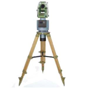
A gyro theodolite is an instrument that combines a gyroscope and a theodolite. It is not limited by time and environment, has simple and convenient observation, high efficiency and high directional accuracy, so it is an advanced directional instrument. As far as mines are concerned, it can completely replace the century-old geometric orientation method that has been used in domestic mine surveying, and overcomes the shortcomings of the geometric orientation method such as occupying the wellbore, causing production shutdowns, and consuming a lot of manpower, material resources, and time. For example, Ericco's ER-GT-02 can be used in mine measurement and has the following characteristics:
1.Orienteering accuracy ≤3.6" (1σ);
2.Pit interference ability is strong, integrated fuselage design, compact structure, stable performance;
3.Has the functions of low lock, automatic zero observation and etc.
If you want to learn about or purchase a gyro-theodolite, please contact us.
More Technical Questions
1.Application of gyro-theodolite orientation in shaft contact measurement
2.Accurate Alignment Method for Gyro Theodolite Calibration System
3.Application of Gyro-Theodolite Orientation in Mine Surveying
4.Effect of latitude on gyroscopic theodolite
5.How To Orient The Gyro Theodolite?
6.What is the Structure of a Gyro Theodolite?
Products in Article