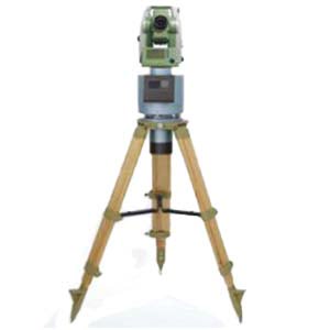
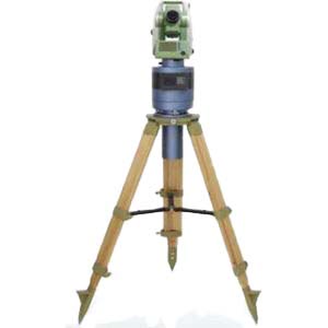
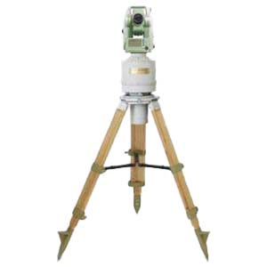
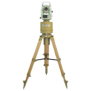
The gyro theodolite is an instrument that uses inertia to autonomously seek north. Its principle is to automatically find and track the geographical north direction based on the north component of the earth's rotation angular velocity, thereby achieving accurate measurement of the azimuth angle of ground points. Compared with traditional northward instruments (such as gyrocompasses and magnetic compasses), gyrotheodolite has the advantages of all-weather use, strong maneuverability, high autonomous orientation accuracy, fast orientation speed, simple and convenient operation, and portability. Gyro-theodolite can be divided into two types from the structure: one is to mount the gyroscope on the theodolite or total station, which is called the top-mounted gyro theodolite; the other is to install the gyroscope on the lower part of the theodolite or total station, which is called the top-mounted gyro theodolite. It is a bottom-mounted gyro theodolite. Gyroscope theodolite can be divided into three levels according to the north-seeking error: the error is within ±5″ for high accuracy; the error is between ±5″ and ±30″ for medium accuracy; the error is greater than ±30″ for low accuracy. With the continuous development of directional measurement technology, the application of gyroscopic theodolite has become more and more widespread, and the requirements for its directional accuracy have become higher and higher.
When establishing a gyro-theodolite calibration system, the azimuth reference must first be established. Generally, a collimator or a self-collimating plane mirror is used as the north azimuth device to determine the angle between the azimuth reference and true north. When using the azimuth reference to calibrate a gyro-theodolite, the center position of the calibrated gyro-theodolite must coincide with the observation center position during astronomical orientation (that is, in the same reference direction), and then aim the calibrated gyro-theodolite at the azimuth reference and take a reading. Calculate gyro-theodolite instrument constants and north-seeking errors.
When centering a gyro-theodolite, there are actually three centers: the gyro-theodolite centering device center, the theodolite center, and the ground mark center. For a mounted gyro-theodolite, the alignment error of the gyro-theodolite is equivalent to the alignment error of the theodolite. For the under-frame gyro-theodolite, the sources of alignment errors of the gyro-theodolite include: ① the alignment error of the gyro-theodolite's own pointing device; ② the eccentricity of the gyro-theodolite's pointing device. During the calibration process of the gyro-theodolite, the centering accuracy of the gyro-theodolite center and the observation center during astronomical orientation directly affects its north-finding accuracy.
The traditional alignment methods mainly include: vertical ball alignment method, optical alignment method, laser alignment method, centering rod alignment method and forced alignment method, etc. Among them, the error of the vertical ball centering method is about ±2mm; the error of the centering rod centering method is about ±1mm. After strict inspection and calibration of the laser plummet and optical plummet, the alignment error is approximately ±0.5mm. The forced centering method using fixing screws has the smallest error, which can generally be controlled at around ±0.1mm.
Since only a single collimator is used in the above traditional centering method, and the target of a single collimator cannot be placed at infinity, and the self-collimating plane mirror cannot be placed at infinity, it is difficult to reduce the centering error, making north search impossible. The accuracy cannot be improved. To address this problem, this paper proposes a high-precision alignment method based on dual targets, designs a matching gyro-theodolite position adjustment mechanism, and verifies the accuracy of this method through experiments.
1.Principle of double target centering method
In order to achieve high-precision alignment between the center of the inspected gyro-theodolite and the observation center during astronomical orientation, a dual-target precise alignment method using two parallel light tubes was proposed. The designed gyro-theodolite calibration system is shown in Figure 1.

Figure 1 Schematic diagram of gyro-theodolite calibration system
The system adopts a dual-target structure. Two 1m parallel light pipes are distributed longitudinally and fixed on two bedrock piers at 180°. Through the parallel light pipe adjustment mechanism, the two symmetrically distributed parallel light pipes generate Adjust the center target point of the infinity target reticle and the center of the gyro-theodolite installation and adjustment seat to a straight line, and then lock them as two north reference points. When calibrating the gyro-theodolite, the center is accurately found by observing two parallel light tubes. The principle is shown in Figure 2.

Figure 2 Principle diagram of accurate centering using dual-objective method
Assume that the beam of collimator M1 and the beam of collimator M2 intersect at point O, and ∠M1OM2 is known. The adjustment process is as follows: ① Place the gyro theodolite on the positioning platform, with its center located at O'; ② Use the gyro theodolite to observe the target M1 and target M2, and obtain ∠M1O'M2; ③ If ∠M1O'M2<∠M1OM2, then along Adjust the position of the gyro-theodolite in the AB direction of the midpoint line AB of ∠M1O'M2, and vice versa; ④ Repeat processes ② and ③ until ∠M1O'M2 = ∠M1OM2. At this time, the position of the center of the gyro-theodolite is consistent with the astronomical orientation. The observation centers coincide. The dual-target method is used to accurately align the gyro-theodolite with the observation center during astronomical orientation. This calibration method does not require the design of a high-precision centering mechanism for the gyro-theodolite. It only needs to add a mechanism near the orientation center that meets the installation and adjustment requirements of the gyro-theodolite. To this end, a mechanism is designed that can realize horizontal two-dimensional displacement adjustment and height and low attitude adjustment of the gyro-theodolite. This mechanism can adjust the center position of the gyro-theodolite to coincide with the observation center position during astronomical orientation with high precision. At the same time, this mechanism can meet the installation requirements of different types of gyro-theodolite, has a wide range of applications and good versatility. The centering mechanism of the gyro-theodolite includes a horizontal displacement adjustment mechanism, a vertical displacement adjustment mechanism, a vertical support frame, etc., as shown in Figure 3. The adjustment range of horizontal displacement and vertical displacement can be designed according to the calibrated gyro-theodolite, and the adjustment amount can be controlled by the micrometric thread. The adjusted angular deviation does not exceed 1″.

Figure 3 Overall structural diagram of the centering mechanism of the gyro-theodolite
2.Analysis of the impact of alignment error on azimuth angle measurement accuracy
When calibrating the instrument constants of a gyro-theodolite, after the calibrated gyro-theodolite is installed on the calibration workbench, there will sometimes be a deviation between the laser plummet of the gyro-theodolite and the central plumb line of the theodolite. This deviation will affect the azimuth angle measurement results. The following analyzes the impact of alignment error on azimuth angle measurement accuracy. Define the known azimuth side direction as the y-axis, and its vertical direction as the x-axis, and establish a rectangular coordinate system, as shown in Figure 4.

Figure 4 Diagram of the impact of alignment error on directional measurement
When δx=δ, it has the greatest impact on the azimuth edge directional measurement. At this time, there is
![]()
It can be seen from equation (1) that the deviation angle is inversely proportional to the distance length of the azimuth side. The deviation angle is proportional to the alignment error δ. Therefore, if you want to reduce the error caused by the deviation angle, the most effective way is to increase the azimuth side length as much as possible, or to minimize the alignment error. However, in actual work, due to the limitations of the test environment conditions, the azimuth side length cannot be infinite. Therefore, in order to improve the measurement accuracy of the azimuth angle, it is necessary to minimize the centering error δ on the azimuth side. Table 1 lists the azimuth angle deviation values caused by the centering error δ on the azimuth edge at some distances.

Table 1 Azimuth deviation values caused by alignment errors
As can be seen from Table 1, the azimuth deviation will be small only when the target is far enough or the centering error is small enough.
Summarize
This paper proposes a dual-target precise centering method that uses two parallel light tubes to measure dual targets and achieve high-precision alignment. This method solves the accuracy limitation problem caused by using only a single parallel light tube in the traditional alignment method. It can make the center position of the gyro theodolite coincide with the observation center position of the astronomical orientation with high precision. It also has the function of target eccentricity correction, successfully improving the accuracy of the gyro. The north direction azimuth angle measurement accuracy of the theodolite makes the calibration of the gyro-theodolite more accurate. A gyro-theodolite centering adjustment mechanism is designed, through which the horizontal and vertical displacements of the gyro-theodolite can be adjusted conveniently and quickly, saving operating time. Moreover, this mechanism can meet the installation requirements of different types of gyro-theodolite, has good versatility, and can be widely used in the field of calibration of gyro-theodolite. ERICCO's gyro-theodolite ER-GT-02 is an ultra-high-precision gyro-theodolite. Our company adjusts the accuracy of this product in real time. If you want to know more about related products, please contact us.
More Technical Questions
1.How To Orient The Gyro Theodolite?
2.What is the Structure of a Gyro Theodolite?
3.What Is The Principle Of A Gyro Theodolite?
4.What Instrument Is A Gyro Theodolite?
5.Do You Know the Application of Gyro Theodolite ?
Products in Article