Fiber optic gyroscope is an optical gyroscope based on the Sagnac effect. It consists of light source, photodetector, beam splitter and optical fiber ring. Temperature affects the accuracy of the fiber optic gyroscope by affecting the performance of its internal components. For details, please check the content of our previous article - Analyze the temperature effect mechanism of fiber optic gyroscope.
1.Discretized optical fiber ring zero-bias error compensation model
The optical fiber ring is composed of optical fibers ranging from hundreds of meters to kilometers in length, wound layer by layer, and each layer can be divided into many turns. It is precisely due to the temperature differences between layers and turns of the optical fiber ring that the temperature phase error of the entire optical fiber ring is accumulated. When establishing a fiber ring discretization bias error compensation model, two different division methods are usually used: division by layer and division by turn. However, the calculation accuracy of the discretized bias error compensation model established in units of layers is not high enough. In order to establish a high-precision bias error compensation model, this article will discretize the optical fiber ring in units of turns. Assume that the entire optical fiber ring contains Q layers of optical fiber, and each layer of optical fiber is divided into P turns. According to the above division method, the optical fiber ring is composed of Q·P turns of optical fiber, and it is assumed that the i-th turn of optical fiber has the same temperature and temperature change rate, The length of the ith fiber turn is mi, and the distance from the starting point of the ith fiber turn to the starting point of the entire fiber ring is ni. The discretized thermally induced rotation rate error in turns is obtained as: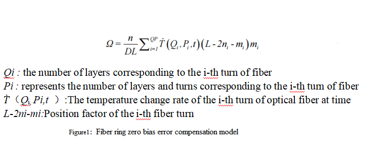
As a rotation-sensitive element in the fiber optic gyroscope, the fiber optic ring has the largest Shupe error caused by temperature changes, accounting for the main part of the temperature drift error of the fiber optic gyro. Therefore, compensating the temperature drift error of the fiber optic gyroscope requires temperature field analysis of the fiber ring as the entry point.
2.Temperature field of fiber optic ring under full temperature excitation
Temperature excitation is applied to the four sides of the optical fiber ring, first maintained at room temperature 25°C for half an hour, then dropped to -40°C at a cooling rate of -1°C/min and maintained for half an hour, and then increased at a temperature increase of 1°C/min. The rate is increased to 60 ℃ and maintained for half an hour, and finally returned to room temperature 25 ℃ at the same cooling rate. The entire process covers the engineering application temperature range of the fiber optic gyroscope as well as the heating/cooling process. The total excitation application time is 19200 s, and the output step is for 192 seconds.
After deriving the temperature parameters of each turn of the optical fiber ring, the change of the optical fiber temperature value of each turn with time can be obtained. As shown in Figure 2, the X-axis is time, the Y-axis is the number of turns of the optical fiber ring after discretization, and the Z-axis is the temperature value of the corresponding optical fiber that changes with time.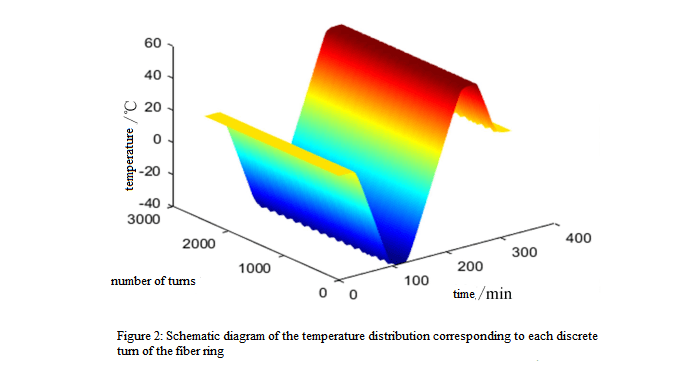
The temperature change rate of each turn of optical fiber changes with time as shown in Figure 3-7. The X-axis is time and the Y-axis is the number of turns of the optical fiber ring after discretization. The Z-axis represents the temperature change rate of the corresponding optical fiber over time.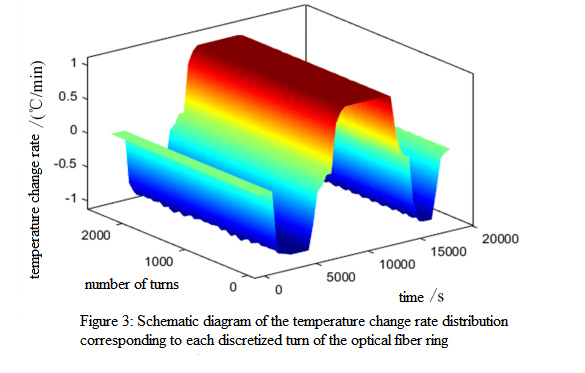
It can be seen from Figure 2 that the temperature of each turn of the optical fiber in the optical fiber ring is in the range of -40~60 ℃, and the peak temperature does not reach the extreme values of -40 ℃ and 60 ℃. This is due to the temperature transfer process There will be a certain degree of loss. As can be seen from Figure 3, the temperature change rate of each turn of the optical fiber in the fiber ring is less than 1 °C/min. After the external temperature reaches a stable value, that is, in the later stage of the insulation stage, the temperature change rate is almost zero. Since the applied temperature excitation is uniformly distributed and the established model is two-dimensional and axially symmetrical and adopts four-level symmetrical winding, the distribution of the temperature field and temperature change rate of the optical fiber ring is relatively symmetrical.
The temperature change rate of each turn of optical fiber during the entire period and the corresponding position factor are respectively brought into the error discretization formula 1. Through MATLAB calculation, the thermally induced rotation rate error of the optical fiber ring under full temperature conditions can be obtained, as shown in Figure 4 shown: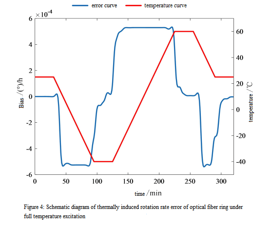
It can be seen that at t=30, 125, and 255 minutes, the external temperature begins to mutate from the stable value, and at the same time, the optical fiber ring also begins to gradually produce thermally induced rotation rate errors. When t=95, 225, and 290 minutes, the outside world gradually approaches a stable temperature value after cooling and heating processes respectively. However, the thermally induced rotation rate error of the optical fiber ring at these moments does not immediately change to zero. On the contrary, it still exists. A certain Shupe error value is due to the fact that although the external temperature has stabilized and the temperature change rate is zero, because the optical fiber ring transmits temperature layer by layer, the temperature change rate of the internal optical fiber coil is not zero. There is still a temperature difference between the inside and outside, which accumulates to form a thermally induced rotation rate error.
3.Polynomial bias error compensation model
It can be seen that the bias error of the fiber optic gyroscope is mainly affected by temperature, temperature change rate and temperature gradient change rate. The temperature change rate is caused by the change of temperature with time, and the reason for the formation of temperature gradient is the uneven change of temperature with time. The temperature gradient mainly exists inside the fiber ring, representing the changes in the internal temperature field, which is difficult to obtain through conventional patch sensors. Moreover, the temperature change rate and temperature play a major role in the temperature drift of the fiber ring output, so most studies usually only two factors, temperature and temperature change rate are considered.
This paper also uses the temperature and temperature change rate factors obtained from different sampling positions to establish a polynomial bias error compensation model. The following high-order polynomial is used to describe the bias error compensation model of the gyroscope, as shown in Equation 5 :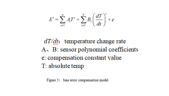
The polynomial model can be expressed in matrix form as shown in Equation 6: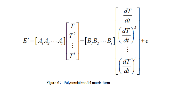
When using polynomials to approximate model fitting, it is usually necessary to solve order problems. Generally, the higher the order of the model, the higher the accuracy; however, as the order increases, the amount of calculation will also increase geometrically, so it is necessary to balance the accuracy of the model and the complexity of the calculation.
4.Summary
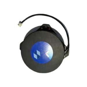
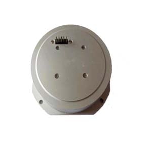
Temperature compensation of fiber optic gyroscope is a tedious and arduous task. Ericco strictly controls its quality and parameters at all times. Currently, our ER-FOG-910 and ER-FOG-851 are currently very popular among customers, very suitable for low-budget customers, if you are interested, you can click on the product below to learn more.
More Technical Questions
1.Analyze the Temperature Effect Mechanism of Fiber Optic Gyroscope
2. Application of Fiber Optic Gyroscope in oil drilling field
3.What causes the FOG measurement error?
4. The Working Principle of FOG
6.Do You Know Fiber Optic Gyroscope and Its Typical Applications?
Products in Article
