The wave of the MEMS sensor market can range from the earliest automotive electronics to consumer electronics in recent years and the coming Internet of Things(IoT) era. Today, a single sensor can no longer meet people's needs for functions and intelligence. Data fusion of various sensors, such as MEMS inertial sensors, MEMS environmental sensors, MEMS optical sensors, and even biological sensors, will become the trend of sensor applications in the new era.
Here we will take MEMS gyroscopes as examples and introduce their work principle briefly.
The traditional mechanical gyroscopes mainly use the law of conservation of angular momentum, that is: for a rotating object, its axis of rotation will not change with the rotation of the bracket that carries it.
Compared with traditional mechanical gyroscopes, MEMS gyroscopes mainly use the principle of Coriolis force (the tangential force experienced by a rotating object when it has radial motion). The published micromechanical gyroscopes all adopt the concept of sensing angular velocity by vibrating objects and use vibration to induce and detect Coriolis forces.
The core of the MEMS gyroscope is a micro-machining mechanical unit, which is designed to operate according to a tuning fork mechanism (The mechanism works by a pair of piezoelectric crystals mounted on the base of the tuning fork to make the tuning fork vibrate at a certain resonant frequency. When the tuning fork of the switch is in contact with the measured medium, the frequency and amplitude of the tuning fork will change. These changes of the tuning fork switch are detected by the intelligent circuit, processed and converted into a switching signal). The driving part of the motor uses the method of electrostatic driving to make the mechanical element oscillate back and forth to generate resonance. The angular rate is converted into the displacement of a specific induction structure by using Coriolis force. The two moving particles move continuously in opposite directions. As long as an angular rate is applied from the outside, a force occurs in a direction perpendicular to the particle's motion. The resulting force displaces the particle in direct proportion to the rate of acceleration applied. A sensor located nearby senses the capacitance change between the stator and the rotor, thereby enabling control. Taking a single-axis offset (YAW) gyroscope as an example, the simplest working principle is explored through the figure below.
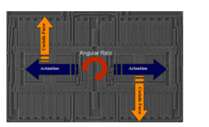
Two identical masses oscillate horizontally in opposite directions, as indicated by the horizontal arrows. When an angular rate is applied externally, a Coriolis force occurs, and the direction of the force is perpendicular to the direction of mass motion. The resulting Coriolis force displaces the sensing mass proportional to the applied angular rate. Because the moving electrode (rotor) of the sensing part of the sensor is located on the side of the fixed electrode (stator), the displacement above will cause a capacitance change between the stator and the rotor, so the angular rate applied at the input part of the gyroscope is converted into an electronic parameter that can be detected by a dedicated circuit - capacitance.
The figure below shows the system architecture of a MEMS gyroscope. The signal conditioning circuit of the gyroscope can be divided into two parts: the motor drive and the accelerometer sensing circuit. Among them, the motor driving part vibrates the driving circuit back and forth through the electrostatic driving method to provide excitation for the mechanical components; and the sensing part measures the displacement generated by the Coriolis force on the sensing mass by measuring the capacitance change.

Of course, MEMS gyroscopes also have other functional modules, such as self-checking function circuits, low power consumption and motion wake-up circuits, etc.
MEMS gyroscope includes Stable control MEMS Gyroscope, North Seeking MEMS Gyroscope, Navigation grade MEMS Gyroscope, which can be applied to Antenna and Line of Sight Stabilization Systems, Integrated Navigation Systems&Industrial Guidance System, Flight Control&Guidance System, Attention Heading Reference Systems (AHRS), Stabilization of Antennas, Cameras&Platforms, Aerial and Marine Geo-mapping / Surveying.
More Technical Questions
1.MEMS gyroscope VS FOG: What’s the difference between them?
2.Feasibility Analysis of MEMS Gyro North Seeking
3.Analysis of Typical Applications of MEMS Sensors
4.Background and Development Status of MEMS Inertial Sensors
5.How to select MEMS gyroscope?
6.What is MEMS Sensor and its Technical Advantages?
Products in Article