


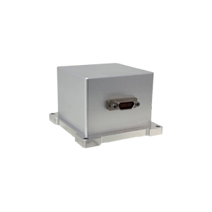
ER-MIMU-053 High Precision Stable Control MEMS IMU
Introduction
IMU is an abbreviation for Inertial Measurement Unit, which mainly consists of a three-axis gyroscope and a three-axis accelerometer. It can measure the angular velocity and linear acceleration of an object in real time, autonomously sensing motion without relying on satellites or external signals, and calculating attitude, tilt angle, heading, and trajectory through integrated algorithms.
Features
Size:70*65*45(with shell)/43.2*43.2*35.5 (without shell and baseboard)
Weight:220(with shell) /100(without shell and baseboard)
OEM Modular design, strong applicability
-40~80°C temperature compensation
High-precision agricultural machinery
Marine Engineering
Construction machinery
Application
Stabilization of Cameras & Platforms
Azimuth, attitude, position measuring and keeping in GNSS-assisted INS
Pitch, roll measuring in AHRS for UAV
Motion survey and keeping in MRU
Attitude & azimuth keeping, positioning in IMU
Guidance, navigation, control in tactical MEMS system
Stabilizing in satellite antenna, target tracking system
Robotic Control & Orientation in autonomous machines, Unmanned vehicles
Specifications
| ER-MIMU-053 | ||
| Item | Parameter | Unit |
| Gyro performance | ER-MIMU-053 | |
| Range | 400 | deg/s |
| Scale Factor at 25°C | 16000 | LSB/deg/s |
| Scale Factor Repeatability (1σ) | <50 | ppm |
| Scale Factor VS Temperature (1σ) | 300 | ppm |
| Scale Factor Non-Linearity (1σ) | <300 | ppm |
| Bias Instability(1σ 25℃) | <0.3 | deg/hr |
| Bias stability (10s 1σ) | <3 | deg/hr |
| Angular Random Walk | <0.125 | °/ √h |
| Bias Repeatability(1σ 25℃) | <3 | deg/hr |
| Accelerometer performance | ||
| Range | 30 | g |
| Bias Stability (10s 1σ) | <75 | ug |
| Bias Repeatability | 100 | ug |
| Bias Temp Coefficient | <20 | ug/℃ |
| Bias Temp Hysteresis | <1.5 | mg |
| Scale Factor Non-linearity | <500 | ppm |
| Scale Factor Month Repeatability | <30 | ppm |
| Scale Factor Temp Coefficient | 100 | ppm/℃ |
| Class II Non-linearity Coefficient | <100 | ug/g² |
| Scale Factor | 250000 | Lsb/g |
| Environment and power | ||
| Operate temperature | -40~+80 | ℃ |
| Storage temperature | -55~+105 | ℃ |
| Power supply | 6~12V | V |
| Power (power supply 6V) | 2 | W |
| Communication interface | RS-422 | |
| Physical characteristics | ||
| Size | 70*65*45(with shell)/43.2*43.2*35.5 (without shell and baseboard) | mm |
| Weight | ≤220(withshell) ≤100(without shell and baseboard) | g |
Dimension

Product composition and working principle
The product is mainly composed of three-axis MEMS accelerometer and gyroscope. The working principle is as follows: the gyroscope and accelerometer data are collected by ARM microcontroller, three high-precision gyroscopes are collected by 1-channel digital interface SPI, and three accelerometers are collected by another 1-channel digital interface SPI. All sensors are calibrated and compensated in software after acquisition.
Product technical characteristics
a)The product is designed for miniaturization and low power consumption;
b)Products with wide voltage design;
Electrical interface
The MIMU inertial measurement unit uses J30J-15ZKN-J output. Electrical pin definitions are shown in Table 1.
Table 1 Pin definition of MIMU high precision inertial measurement unit
| Pin number | Electrical characteristic | Signal direction | Remark |
| 1 | VCC | Power + | 6-12V |
| 2 | Retain, disable | ||
| 3 | GND | Power supply - | |
| 4 | Retain, disable | ||
| 5 | Retain, disable | ||
| 6 | RS422,TX+ | ||
| 7 | RS422,TX- | ||
| 8 | RS422,RXD+ | ||
| 9 | RS422,RXD- | ||
| 10 | Retain, disable | ||
| 11 | Retain, disable | ||
| 12 | Retain, disable | ||
| 13 | Retain, disable | ||
| 14 | Retain, disable | ||
| 15 | Retain, disable |
Communication protocol (adjustable baud rate)
RS-422 serial interface, default baud rate 921600bps, 8bit data bit, no check bit, 1bit stop bit, The default data refresh rate is 400Hz.
Data output protocol
| Byte | Define | Note | Range | Units | Measuring scale |
| 1~4 | Protocol Head | EB8055AA | |||
| 5~8 | X axis angular rate | int | -400~+400 | deg/s | 500/(2^31-1) |
| 9~12 | Y axis angular rate | int | -400~+400 | deg/s | 500/(2^31-1) |
| 13~16 | Z axis angular rate | int | -400~+400 | deg/s | 500/(2^31-1) |
| 17~20 | X axis accelerated speed | int | -30~+30 | m/s^2 | 300/(2^31-1) |
| 21~24 | Y axis accelerated speed | int | -30~+30 | m/s^2 | 300/(2^31-1) |
| 25~28 | Z axis accelerated speed | int | -30~+30 | m/s^2 | 300/(2^31-1) |
| 29~32 | IMU temperature | float | |||
| 33 | Frame count | unsigned char | 1~255 | ||
| 34 | Sum | unsigned char | Byte 3~60 summation |
Test interface operation description
The user installs the test interface on the computer,open xInsConnect.exe, as shown below.
Click "COMCFG" to configure the baud rate of RS422 serial port, which is the COM port required; Click the "Open" button to open the RS422 communication interface and power on the IMU.
The Angle data of X,Y,Z gyro "GX,GY,GZ", the data of X,Y,Z accelerometer "ACCX,ACCY,ACCZ" will be displayed on the interface. The temperature data of IMU will be displayed in the "TX" box. Click "CAL" box to set the data update rate of the interface to 100. The "Counter" box displays the frame serial number for each frame of data.

Precautions for use
1)Installation error description
Internal orthogonal compensation has been carried out for the whole product. If the platform used by the product cannot guarantee the accuracy of the benchmark after installation, please compensate the installation error accordingly.
2)Installation and protection
When the product is installed, it should be tightly installed parallel to the base level of the carrier installation (the installation error with the base level should be less than 0.05°).
Because the product is a precision test instrument, although there is a shell protection, in order to protect the product damage, users should handle gently. The use and movement of the product should avoid falling, and be sure not to let the product and other components in the use of serious impact, to ensure the accuracy of the product datum requirements.
After sale
Please do not disassemble this product without our company's permission, if disassembled without permission, the warranty will be invalid.
If there is any technical problem or failure in the use of the product, you can contact the corresponding technical personnel of our company.
Application Techniques
1.Do you know the core components that give precise control to automated equipment
2.High-performance IMU: A New Benchmark for Precise Measurement and Control
3.Industrial Versatile Tool: High Cost-Performance IMU Meets Diverse Needs
4.Flight safety secrets: The core role of high-precision IMUs in aviation
5.Revolutionizing drone navigation: How to redefine high performance and low cost
6.From flight control to fault diagnosis, how does IMU dominate drones?
More Products
 North-Seeking MEMS IMU
 High Accuracy North-Seeking MEMS IMU
 North Seeking Mems Imu For Gyro Tools
 North-seeking MEMS IMU
 Economical MEMS Gyroscope