


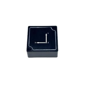
ER-MIMU-M01 Low Cost MEMS IMU
Introduction
M01, with its economical price, has become the first choice for users who value cost-effectiveness. Although its precision is relatively the lowest among the three products, it is still equipped with a 3-axis gyroscope and a 3-axis accelerometer, which can provide users with basic acceleration and angular velocity measurement functions. It meets the needs of application scenarios with low precision requirements, such as motion control of simple toy robots and preliminary monitoring of object motion status by low-cost sensor nodes.
Product Features
Economical and practical: With a relatively low price, it is suitable for application scenarios with low precision requirements and limited budgets, such as some simple toy robots and low-cost sensor nodes. It can provide users with basic attitude and motion sensing functions.
Low-power operation: While ensuring high performance, it achieves lower power consumption, effectively extending the battery life of devices. It is particularly suitable for mobile devices and IoT terminals that rely on battery power and have high requirements for battery life.
A cost-effective choice: On the premise of ensuring certain precision and performance, the M01C series focuses on optimizing the cost structure, providing a cost-effective solution for customers who are price-sensitive but need inertial measurement with a certain level of precision. For example, in fields such as some consumer robots and toy drones, it can not only meet basic functional needs but also control costs, thereby enhancing product competitiveness.
Application Fields
- UAVs and aeromodels: Provide accurate attitude and acceleration data for aircraft to achieve stable flight, precise positioning and route planning, and improve flight performance and safety.
- Robot field: Help robots achieve precise motion control, balance adjustment and environmental perception, enabling them to flexibly and stably complete tasks in complex environments, such as autonomous navigation of service robots and high-precision operations of industrial robots.
- Wearable devices: Used to monitor human movement posture, step counting, movement trajectory recording, etc., providing accurate data for applications such as health monitoring and sports analysis, and enhancing user experience.
- Industrial automation: Play an important role in motion monitoring and control of automated production line equipment, equipment vibration detection, etc., helping to improve production efficiency and ensure the safe operation of equipment.
Product Performance Indicators
The performance indicators of the micro inertial measurement unit are shown in Table 3.1.
| Type | M01A | M01B | M01C | Unit | |
| Gyro | Measuring range | ±500 | ±500 | ±500 | °/s
|
| Bias instability | ≤2 | <2.5 | <3 | °/h
|
|
| Bias stability (1 σ) | ≤8 | <10 | <15 | °/h
|
|
| Bias repeatability (1 σ) | ≤8 | <10 | <15 | °/h
|
|
| Angle random walk | ≤0.15 | <0.17 | <0.21 | °/ √h | |
| Accelerometer | Linear acceleration measurement
range
|
±16g | ±16g | ±16g | g |
| Bias stability | ≤0.2 | 0.28 | 0.4 | mg | |
| Bias repeatability | ≤0.2 | 0.3 | 0.5 | mg | |
| Electrical Specification | Voltage | 3.3±0. 15 | 3.3±0. 15 | 3.3±0. 15 | V |
| Operating temperature range | -45℃~+85℃ | -45℃~+85℃ | -45℃~+85℃ | ℃ | |
| Else | Weight | <9 | <9 | <9 | g |
| Size | 23.7*23.7*9.9 | 23.7*23.7*9.9 | 23.7*23.7*9.9 | mm | |
| Shock resistance | ≥2000 | ≥2000 | ≥2000 | g | |
| Vibration | ≥20g | ≥20 | ≥20 | grms | |
| Electrical interface | UART | UART | UART | - | |
| Connector(--) | FTMH-110-02-L-DV-ES | FTMH-110-02-L-DV-ES | FTMH-110-02-L-DV-ES | - | |
Note: The ranges of the gyroscope and accelerometer can be customized. The customizable range of the gyroscope is ±125dps-±4000dps; the customizable range of the accelerometer is ±2g-±16g.
Product Outline Dimensions
The outline dimensions of the micro inertial measurement unit are shown in Figure 2.1.
Figure 2.1 Outline Dimension Drawing
4.Electrical Interface and Communication Protocol
4.1 Electrical Interface Definition
The interface is a Samtec connector. The product end model: FTMH-110-02-L-DV-ES, defined as shown in Figure 4.1 and Table 4.1. Mating end model: CLM-110-02-L-D.
Figure 4.1 Output Interface Pin Definition Diagram
Table 4.1 Output Interface Pin Definition
| Pin | Pin definition | Pin definition |
| 7 | SOUT | UART output |
| 9 | SIN | UART input |
| 10,11,12 | Vcc | power supply 3.3V |
| 3,4,8,15 | GND | power ground |
Note: The SOUT and SIN of the UART output are based on the product.
4.2 Communication Protocol
The default baud rate of the micro inertial measurement unit is 460800, with 1 start bit, 8 data bits, 1 stop bit, no parity check, and a refresh rate of 400Hz. Its output frame format is shown in Table 4.2.
Table 4.2 Output Data Frame Format
| serial number | project | byte | type |
| 1 | FH(frame header) | 1 | 0xAA |
| 2 | 1 | 0x55 | |
| 3 | GYRO_X | 4 | float |
| 4 | GYRO_Y | 4 | float |
| 5 | GYRO_Z | 4 | float |
| 6 | ACCL_X | 4 | float |
| 7 | ACCL_Y | 4 | float |
| 8 | ACCL_Z | 4 | float |
| 9 | Temper | 4 | float |
| 10 | Frame end | 1 | 0xEB |
| 11 | 1 | 0x80 |
5. Installation Requirements
It is recommended to use M2.5 or M2 screws for fixing. The mounting hole distance refers to Figure 2.1, and M2.5 or M2 threaded holes are processed on the mounting surface.
6. Usage Steps
(1) Set the input voltage according to the specified voltage of the product, and power on the product according to the electrical interface definition;
(2) Set according to the communication protocol, and check whether the output signal meets the performance index requirements. The product can be used normally if the installation and electrical connection are correct.
7. Precautions
(1) Pay attention to the product's electrical interface definition. When using, please strictly follow the arrangement of the terminals to avoid wrong connection;
(2) The product is a precision measuring device. During operation, be careful not to have impacts, collisions and other unexpected situations beyond the product's bearing range;
(3) The installation of the product has a great impact on angular velocity measurement. To avoid introducing installation errors, the installation plane is required to have good flatness;
(4) To ensure measurement accuracy, the product must be installed firmly and reliably to avoid measurement errors caused by looseness;
(5) When installing and using the product, attention should be paid to anti-static protection, and it is recommended to wear an anti-static wristband;
(6) Please operate in strict accordance with the requirements of this manual, confirm that the external environment is consistent with the use requirements. If problems occur, do not open the product cover or change the internal structure of the product. If there are any problems, please contact our technical personnel in time.
Application Techniques
1.Do you know the core components that give precise control to automated equipment
2.High-performance IMU: A New Benchmark for Precise Measurement and Control
3.Industrial Versatile Tool: High Cost-Performance IMU Meets Diverse Needs
4.Flight safety secrets: The core role of high-precision IMUs in aviation
5.Revolutionizing drone navigation: How to redefine high performance and low cost
6.From flight control to fault diagnosis, how does IMU dominate drones?
More Products
 North-Seeking MEMS IMU
 High Accuracy North-Seeking MEMS IMU
 North Seeking Mems Imu For Gyro Tools
 North-seeking MEMS IMU
 Economical MEMS Gyroscope