

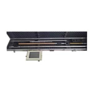
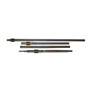
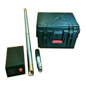
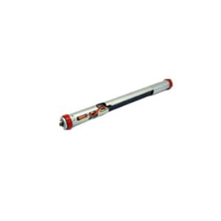
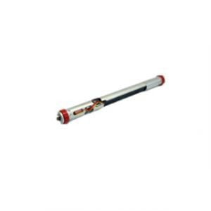
ER-OS-07 High Precision Fluxgate Directional Assembly
Introduction
The ER-OS-07 High Precision Fluxgate Directional Assembly is designed to enable high accuracy measurement of the tool face (roll), inclination and azimuth orientation angles in borehole logging and drilling applications.
The product consists of a 3-axis flux-gate magnetometer and a 3-axis accelerometer. It is powered by a wide DC voltage of 10V~36V and is digitally transmitted through a UART asynchronous transmitter. ER-OS-07 has a temperature compensation function, which can make the system reach the accuracy of ±0.1°, tool face ±1° and azimuth angle ±0.3°.
The maximum transmission rate of the magnetometer and accelerometer output is 6 times per second, and the direction angle is 4 times per second. ER-OS-07 communicates with the outside world through the UART interface. The operator can change the baud rate by setting the data bit in E2 PROM.
You can choose between two communication protocols according to specific requirements:
(1) Binary system: In this system, the user needs to send a data request and ER-OS-07 responds with multiple data packets.
(2) ASCII: The ASCII protocol obtains data by sending ASCII characters to ER-OS-07. The data returned by ER-OS-07 is transmitted in ASCII data stream, so it can be easily displayed on the video terminal.
Features
Temperature: -40℃~150℃
Accurate measurement under strong vibration environment with 16g peak value (20Hz~100Hz)
Shock resistance 1000g, vibration resistance 20grms
Digital data transmission
With minimum size of Φ31mm×384mm (customized to different needs)
Applications
Directional drilling, geological steering
MWD/LWD
Specifications
| Measurement accuracy | |
| Inclination | ±0.1° |
| Toolface | ±1°@INC≥10° |
| Azimuth | ±0.3°@INC=90° |
| ±1°@INC≥10° | |
| ±2°@INC≥5° | |
| Electrical interface | |
| Input voltage scope | 10V~36V |
| Input current | <75mA@+15V |
| Digital interface | UART/RS232 (selectable) |
| Baud rate | 9600~115200 |
| Communication proposal | ASCⅡ or binary |
| Working temperature | |
| Operating temperature scope | -40℃~150℃ |
| Storage temperature scope | -50℃~160℃ |
| Shock | 1000g, 1ms half-sine |
| Vibration | 20g |
| Outline parameters | |
| Diameter | 31mm |
| Length | 384mm |
| Connector | MDM9SH003P (MDM15PH003F) |
| Matching connector | MDM9PH003L (MDM15SH003L) |
Dimension

Application Techniques
1.Three Signal Transmission Methods of MWD Inclinometer While Drilling
2.Development of MWD for Directional Drilling
3.What Is The Difference Between MWD And LWD?
4.What Is The Principle Of MWD?
5.Fluxgate Directional Assembly: Structure and Design of Fluxgate Acquisition System
6.How to apply MEMS sensor in Oil & GasᅵAerospaceᅵAHRSᅵUAV?
More Products