Fluxgate directional assembly contains fluxgate sensors that measure well angle, tool face angle and azimuth angle. It is mainly used in MWD (Measurement While Drilling) and is an important component of MWD. Fluxgate directional assembly collects information through acquisition system. This paper introduces the structure and design of fluxgate acquisition system.
System structure and principle
The fluxgate acquisition system introduced in this paper requires the system to have rich data interfaces in order to facilitate the system integration and data fusion processing. On the other hand, it has geographical. location information and high-precision time information, so as to facilitate the post-processing and data fusion. In order to meet the above requirements, the block diagram of the acquisition system is shown in Figure 1.
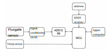
Figure 1 Schematic diagram of the acquisition system
The fluxgate probe is used to measure the three-component magnetic field. After signal conditioning, the signal is converted digitally by the ADS1299. The main controller STM32 reads the AD sampling data for real-time processing, synchronizes with the positioning time information of the GNSS receiver and the temperature data of the temperature sensor, and sends it to the upper computer for display and storage.
System design
1.ADS1299 circuit
The peripheral circuit of the ADS1299 includes the sampling clock, reference voltage and MCU interface. The ADS1299 has an integrated sampling clock and reference voltage with a sampling clock accuracy of ±2.5% and a reference voltage temperature drift of 35ppm/℃. In order to ensure the sampling accuracy and frequency accuracy of the acquisition system, an external reference clock and an external reference voltage source are designed. The external reference voltage source uses REF5045 with temperature drift of 5 ppm/℃, and the clock uses a temperature-compensated crystal oscillator with a total frequency difference of 20 ppm.
The MCU interface of ADS1299 is SPI interface and control signal interface. The MCU can configure the working mode of the ADS1299 through SPI and read the sampled data in real time. The control signal interface is used to realize the power-on reset, startup conversion and conversion completion mark of the ADS1299. The circuit schematic diagram of ADS1299 is shown in Figure 2.
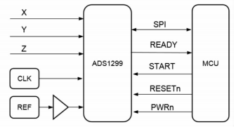
Figure 2 Schematic diagram of sampling and processing circuit
2. Filter circuit
The geomagnetic field is a slowly changing field, and there are a variety of interference sources in the environment, which will affect the magnetic measurement results. For this reason, the signal conditioning circuit of the sampling system is designed. On the one hand, it is used to filter out high-frequency interference signals, and on the other hand, it is used to match the signal input requirements of the analog-to-digital conversion chip.
The input signal voltage range of the fluxgate sensor is -10 V to +10 V, and the signal bandwidth is less than 10 Hz when the carrier is moved for measurement. In order to satisfy the requirement of geomagnetic signal filtering, a second-order active low-pass filter is designed in this paper. The amplifier selected low noise AD8675, the selection of ± 15V bipolar power supply, the circuit schematic diagram is shown in Figure 3.
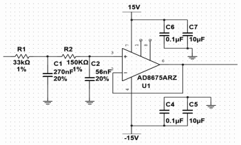
Figure 3 Low-pass filter circuit
3. Embedded processing circuit
The sampling system uses STM32F407 single chip microcomputer as the processor, its SPI clock rate up to 42 MHz, and has a lot of peripheral interfaces such as serial port, CAN bus and USB, which can meet the requirements of the sampling system. The processor circuit of the acquisition system is shown in Figure 4. The processor uses an external 25 MHz clock; An external EERPOM is designed to store the configuration parameters of the sampling system. The processor receives the data of GNSS receiver through UART and communicates with the host computer through RS422 serial port.
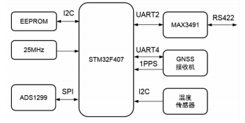
Figure 4 Block diagram of embedded processing circuit
Conclusion
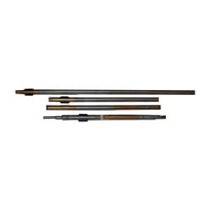
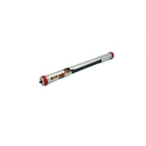
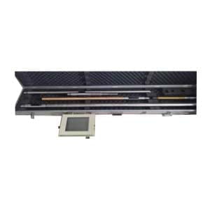
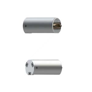
This paper introduces the structure and design of fluxgate acquisition system. Through system acquisition, well angle, tool face angle and azimuth angle are tested. Fluxgate directional assembly can play an important role as a component in the field of MWD and directional drilling. Fluxgate directional assembly are also divided into dynamic and static measurement methods, wired and wireless two forms. For example, the ER-DOS-03 is a dynamic measurement Fluxgate directional assembly that contains a three-axis fluxgate sensor and a three-axis accelerometer. The ER-OS-07 and ER-WOS-08 are wireless and wired Fluxgate directional assembly, respectively, and they have higher temperature models, which can reach 180 ° C.
I hope you have some knowledge about Fluxgate directional assembly and fluxgate acquisition systems. If you are interested in more knowledge, please contact us.
More Technical Questions
1.Fluxgate Directional Assembly: The Working Principle of Fluxgate
2.How Do Fluxgate Directional Assembly work in MWD
3.GWD - Gyro-while-drilling Technology Superior to Traditional MWD
4.Three Signal Transmission Methods of MWD Inclinometer While Drilling
5.What Is The Difference Between MWD And LWD?
6.What Is The Principle Of MWD?
Products in Article