



Introduction
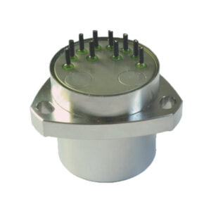
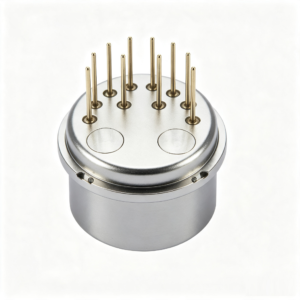
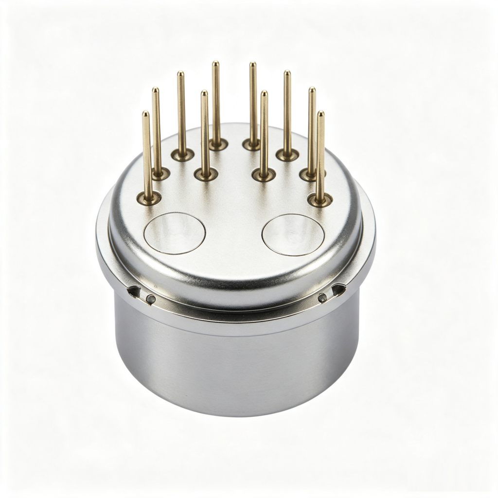
The ER‑QA‑03F series is a compact, high‑temperature‑resistant, and vibration‑resistant dedicated sensor for petroleum inclinometers. Featuring a circular flange design, this product offers excellent repeatability, start‑up performance, high‑temperature tolerance, vibration resistance, and high reliability. It is suitable for both static and dynamic testing and also serves as a standard vibration sensor.
The product employs a unique miniaturized, high‑temperature‑resistant, and anti‑vibration design, combined with advanced packaging technologies and dedicated circuitry. An internal temperature sensor can be built in according to user requirements for bias and scale‑factor compensation, thereby reducing the influence of ambient temperature.
Since its launch in 2012, the product has matured and achieved widespread application, especially in large‑scale use in petroleum drilling inclinometry.
Specification
| Parameters | ER-QA-03F01 | ER-QA-03F02 |
| Range | ±30g | ±30g |
| Threshold value | 30μg | 30μg |
| Bias | ≤(±20 mg) | ≤(±20 mg) |
| Scale factor | 2.0±0.1mA/g | 2.0±0.1mA/g |
| Scale factor error | 5% | 5% |
| Second-order nonlinear coefficient | ≤±20μg /g2 | ≤±50μg /g2 |
| 0g 4 hours short-term stability | ≤30 μg | ≤40 μg |
| 1g 4 hours short-term stability | ≤30 ppm | ≤40 ppm |
| Bias comprehensive repeatability (1σ, 1month) | ≤150 μg | ≤220 μg |
| Scale factor comprehensive repeatability (1σ , 1month) | ≤150ppm | ≤220 ppm |
| Nonlinear coefficient repeatability (1σ , 1month) | ≤±40 μg /g2 | ≤±50 μg /g2 |
| Bias temperature coefficient | ≤±80 μg /℃ | ≤±150 μg /℃ |
| Scale factor Temperature coefficient | ≤±100 ppm /℃ | ≤±200 ppm /℃ |
| Noise(Sampling resistance is 840Ω) | ≤8mv | ≤8.4mv |
| Natural frequency | 350~800 Hz | 350~800 Hz |
| Bandwidth | 800~2500 Hz | 800~2500 Hz |
| Vibration | 25g(20-2000Hz) | 25g(20-2000Hz) |
| Shock | 1000g,0.5ms,1/2sin | 1000g,0.5ms,1/2sin |
| Operating temperature range | -40℃+150℃ | -40~+180℃ |
| Storage temperature range | -60-+180℃ | -60~+200℃ |
| Power supply | ±12~±15V | ±12~±15V |
| Current consumption | ±20mA | ±20mA |
| Size | Ф18.2X16mm | Ф18.2X16mm |
| Weight | 25g | 25g |
Dimension
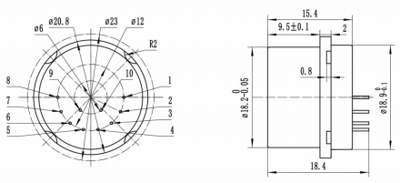
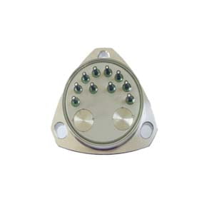
The electrical interface relationship of the servo circuit is shown in Table 1. The terminal arrangement and description should comply with the requirements of Figure 1. The terminal arrangement is a bottom view (pins upward).
Table 1 Servo circuit electrical interface relationship
| Pinout
Serial Number |
symbol | Pin function | Pinout
Serial Number |
symbol | Pin function |
| 1 | ML | Signal output terminal | 6 | Tse | PT1000 First End |
| 2 | MH | Current test terminal | 7 | C ext1 | Differential capacitance detection terminal 1 |
| 3 | V- | Negative power supply terminal | 8 | C ext2 | Differential capacitance detection terminal 2 |
| 4 | V+ | Positive power supply terminal | 9 | VO- | PT1000 second terminal |
| 5 | GND | ground | 10 | VO+ | Regulator positive output(+9V) |
Application Techniques
1.Choosing a Good Quartz Accelerometer is Easier to Maintain
2.How does the Quartz Accelerometer Work?
3.How do parameters affect the performance of the quartz accelerometer?
4.Application of Quartz Accelerometer in UAV and Positioning System
5.Application of Quartz Accelerometer
6.Multi-Dimensional Understanding of High Precision Quartz Accelerometer
More Products