Definition
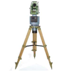
Gyro theodolite is a directional positioning instrument, which is composed of two parts: gyroscope and theodolite. This instrument is a theodolite with a gyroscopic device used to determine the true north azimuth of the line. It uses the precession and fixed axis of the gyroscope itself, sensitive to earth rotation, and can quickly and accurately give the true north position of the measured point anywhere within 75° north and south latitude, so as to determine the true north azimuth of any target.
Gyro theodolite is used to measure the true azimuth simply and quickly, and is not limited by time. It is often used to measure roads, railways, tunnels and mines. The above content is for reference only, if you need detailed information and data of gyrotheodolite, it is recommended to consult relevant professional books or consult experts in the field of surveying and mapping.
1.North seeking working principle of Gyro Theodolite
1.1 Earth’s rotation and gyroscopic precession
The earth is a constantly rotating object. It rotates around the earth's axis with ωE; therefore, all objects on the earth also rotate at the same time. When you look down at the Earth from above the North Pole, you can find that the Earth's rotation is counterclockwise, and the angular velocity vector ωE points toward the North Pole along the Earth's rotation axis. Assume that the ground point P is at a position with a latitude of ϕ, and the angle between the direction of the earth's rotation angular velocity vector and the horizontal plane at this point is ϕ. At the ground point P, the ωE vector can generally be decomposed into a horizontal component vector ω1 (along the ground The tangent direction of the meridian where the point is located) and the vertical component vector ω2 (along the vertical direction of the meridian where the ground point is located).
Figure 1(b) shows the position of the auxiliary celestial sphere above the ground. Assuming that the center of the earth is O, the earth can be regarded as a point for various celestial bodies other than the earth. If the gyroscope and the observer are both at point O, and the x-axis of the instrument is in the horizontal direction, east of the true meridian, the angle between the two is α. which level
The formula for calculating the components is


Figure 1 Schematic diagram about angular velocity of earth rotation
The rotational component ω2 is the speed at which the gyro rotates around the Z-axis at its ground position. The most direct experience is that the northern end of the meridian moves toward the west. It can be called the vertical component of the rotation of the Earth's sphere. What an observer on the earth experiences is the relative relationship between the heights of other planetary bodies and the sun in inertial space. Therefore, the calculation formula for the vertical component of angular velocity is as follows
![]()
In order to specifically express the motion of the gyroscope due to the rotation of the earth, the horizontal rotation component ω1 is further decomposed into factors ω4 (along the x-axis direction) and ω3 (along the y-axis direction), where

Considering that when the earth rotates as a whole, the gravitational moment on the instrument will push the gyro's polar axis to move along the x-axis, generating a force that returns to the meridian plane where the gyro is located; when the polar axis moves to the ground plane due to the force of the hanging weight (as shown in Figure 1(a) )), does not produce a hanging weight moment, so it has no effect on the change in the orientation of the x-axis [24]. However, since the earth is in a state of constant rotation, the gyroscope main axis and the ground plane are not parallel to each other at the next moment. Intuitively speaking, the positive direction of the x-axis of the gyroscope main axis is raised again relative to the ground, and the angle between it and the ground is different. θ (see Figure 1(b)). Therefore, the moment effect caused by the hanging weight will push the main axis of the instrument to precess in the direction of the meridian plane. Assume that the gravity of the sensitive part of the rotor is P and the center of the rotor is located at position O1. Let the distance between the center of gravity and point O be l. Therefore, considering the rotation of the ground plane around the y-axis, the final rotational moment is:
![]()
The precession angular velocity of the x-axis of the instrument spindle is

Therefore, the main axis of the instrument always precesses toward the meridian under the action of the effective factor component ω3 of the earth.

Figure2 Relationship between axis of gyroscope and heavy torque
2.Orientation method of Gyro Theodolite
The orientation process of the Gyro Theodolite can be divided into coarse north-seeking orientation and fine north-seeking orientation. In coarse north seeking orientation, gyro orientation generally uses the two reversal point method, the three-point timing method, the quarter period method, etc. The most commonly used methods for precise north orientation include the four-point method, the Midheaven method, the integral method, the Shula average method, the Thomas average method, etc.
2.1 Reversal point method
The reversal point method is a gyro orientation measurement method in which the aiming part of the gyro is at the tracking target. It is generally used on rack-mounted suspended Gyro Theodolites. In the process orientation using the reversal point method, we are required to always keep the sighting part in a tracking state, observe and record multiple sets of swing endpoint values, and use this method to calculate the gyro north-seeking direction value. The reversal point method gyro orientation As shown in Figure 3.

Figure3 Method of Observation with Reversal Point
2.2 Zhongtian method
When using the mid-heaven method for gyro directional observation, since the sighting part of the gyro theodolite is in a fixed state at this time, this is a twisted observation. This method requires that when we initially place the gyro, the north direction of the gyro must be approximately within 15′ of true north. When using the mid-heaven method for gyro orientation, generally first fix the sighting part on the gyro theodolite at an approximate north direction N', and record the value of the approximate north direction. Zhongtian method gyro orientation requires that during the entire orientation process, the upper sighting part of the instrument must have a fixed direction and not change.
When using the Midheaven method for observation, the observation time is required to be at least one cycle, and at the same time, the Midheaven time of the Midheaven method can be read through cooperation; usually five Midheaven values can be used for observation and recording, and the untracked swing period also needs to be obtained.
2.3 Integration method
The principle of integral orientation is the same as that of mid-heaven orientation. It also needs to be initially placed in the basic north direction to proceed to the next step. However, the different characteristics of the two methods of orientation are: the Zhongtian method collects multiple point values in the gyro swing for calculation, and has discrete characteristics. The principle of the integration method is to read and capture a large amount of complete data of the gyro's precession swing when the gyroscope precesses, and comprehensively consider the information of each sampling point, so the final north-finding effect is also the best.
2.4 Thomas average method
The Thomas average method is a north-finding algorithm used by gyroscopes when accurately seeking north. The gyro average method collects the values of more than 7 reversal points of the gyro swing stability value, and finally calculates the value of the gyro's north direction through formula calculation. Since the data collected by this method is relatively comprehensive and complete, this method is widely used in the gyro. The total station's accuracy in finding north also works well.
2.5 Damping method
The damping method north-seeking orientation is a north-seeking method that uses the reverse torsional moment when the gyroscope swings, ultimately causing the sensitive part of the gyro to swing rapidly and converge to the true north direction; during this process, the sighting part needs to track the sensitive part at all times. The swing finally converges with the north direction together with the sensitive part. There are many types of damping torsion torque, generally such as electromagnetic torque, suspension torsion torque, etc. The general principle of damping torque is: when the gyro swings to the reversal point, the personnel performs precise tracking and observation of the reversal point through the horizontal micro-motion spiral of the total station, lasting 5-7 times, until the swing amplitude gradually decreases, and finally stabilizes in the north direction. .
Summarize
This chapter mainly introduces the definition of the Gyro Theodolite and the working principle of north seeking, explains in detail the north seeking orientation process of the Gyro Theodolite, and analyzes the orientation principles and accuracy of several orientation methods of the Gyro Theodolite. If you want to learn about or buy a Gyro Theodolite, ERICCO's Gyro Theodolite, such as ER-GT-02, can achieve ultra-high-precision north seeking. Its measurement principle is the integration method, which has strong anti-interference ability and stability. High characteristics. The gyro-theodolite adopts an integrated body design (built-in battery), with compact structure and stable performance. It has functions such as low-level locking, automatic zero-position observation, automatic north seeking, automatic limit, and wide temperature compensation. It is gradually iterating the limiter to provide the north seeking accuracy of the reference plane azimuth angle and reduce the north seeking time.
Welcome to consult and purchase.
More Technical Questions
1.Application of gyro-theodolite orientation in shaft contact measurement
2.Accurate Alignment Method for Gyro Theodolite Calibration System
3.Application of Gyro-Theodolite Orientation in Mine Surveying
4.Effect of latitude on gyroscopic theodolite
5.What is the Structure of a Gyro Theodolite?
6.How To Orient The Gyro Theodolite?
Products in Article