As an important feedback link in the control system, the inertial measurement unit's delay characteristics of its gyroscope channel and accelerometer channel are an important technical indicator. In actual attitude control and navigation solution systems, the output delay of the inertial measurement unit is required to be as small as possible. The better the real-time performance, the easier it is for the control system to make timely and accurate attitude corrections. Then studying the measurement method of output delay is the key to accurately evaluate the dynamic performance of inertial measurement equipment. At present, conventional delay measurement only examines the output delay of the gyro channel, and does not involve the time asynchronous problem between the acceleration channel and the angular velocity channel. In order to make up for this shortcoming, this paper proposes an angular vibration test based on the sinusoidal swing motion of the angular vibration table. On the basis of the process, the synchronous acquisition of three accelerometer channel signals is added, the raw data of the gyroscope and accelerometer are converted into the frequency domain, and then the characteristic frequency points are extracted. Finally, the time delay is calculated from the phase angle of the characteristic frequency point and the time synchronization of the inertial device is achieved of calibration.
1.Delay analysis
The output delay of the inertial measurement unit is mainly affected by the superposition of its own structural transmission , the response of the gyroscope and meter-added inertial device, digital filtering, data transmission and other links.
Structural transmission: In order to ensure a good working environment for the inertial instrument, rubber shock absorbers are usually elastically installed between the inertial instrument and the measured carrier. The response delay for the angular velocity and linear velocity transmission in the low frequency band is negligible, but for high-frequency excitation There is a certain delay in response.
The response of the inertial device itself: Due to the influence of the structure and the sensitivity of the electronic devices, the gyroscope and the meter-added inertial device themselves have a certain delay when they are sensitive to external excitation.
Digital filtering: The digital signal processing of the gyroscope itself will cause delays to the entire system during the step height filtering and output signal filtering stages, reducing the ability of the inertial instrument to track external inputs, and there is some inherent delay. After the inertial measurement unit collects instrument data, it needs to undergo low-pass filtering to remove signal noise. If the filter order is high, the phase group delay generated will affect the system response time. Taking the 50th-order FIR low-pass filter as an example, from the amplitude-frequency phase-frequency curve of the digital filter in Figure 1, we can find that: 2kHz sampling data, the phase delay generated by the excitation below 200Hz in the phase-frequency curve is linear, then the group The delay is a fixed constant value of about 12.5ms.

2.Time synchronization analysis
Research on traditional strap down inertial navigation system algorithms is based on ideal measurements from gyroscopes and accelerometers. However, in an actual IMU, the signal output of each inertial device may be asynchronous in time. The output time of the gyroscope may be later than the output time of the accelerometer, or it may be faster than the output time of the accelerometer. This is because the physical limitations of the sensor inside the inertial measurement unit will affect the conversion of the bandwidth signal, ultimately resulting in the time of the output parameter. Delay. The frequency band width of fiber optic gyroscopes is generally several thousand Hz, which is much higher than the frequency bandwidth of accelerometers, and will eventually be processed to a unified output frequency. This processing process may also cause desynchronization of the actual output signal. In addition, the filter before the AD converter may also cause additional delays in the gyroscope and accelerometer signals, which are determined by factors such as the time it takes the sampled information to be transmitted to the computer. In addition, the inertial device also needs to be processed by some auxiliary hardware to make the inertial device output a more accurate signal. Therefore, it is necessary to compensate for the sum of all physical delays of the accelerometer and gyroscope and additional software and hardware delays, that is, to test the time delay parameters through SINS. The calibration results in the process are partially compensated to synchronize the accelerometer and gyroscope outputs.
3.Measurement method
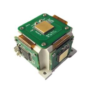
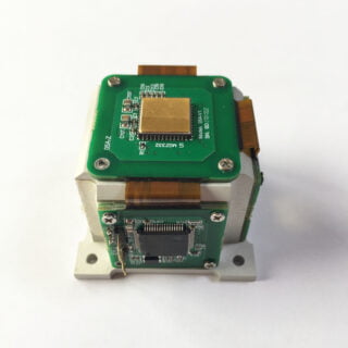
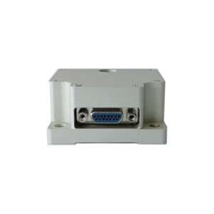
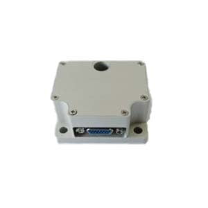
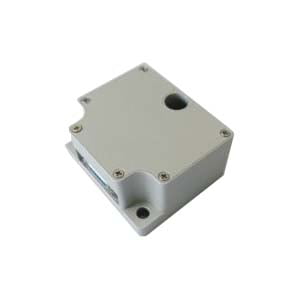
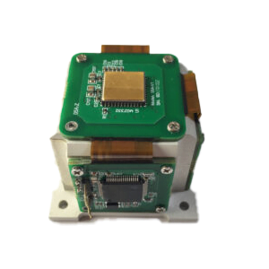
In order to fully measure the time asynchronous parameters between the three accelerometers, the time asynchronous parameters between the three gyroscopes, and the asynchronous time error between the inertial device and the standard output, the analog signal output by the closed-loop angular vibration table is used as the standard output time reference. The product under test is fixed at a certain distance from the center of the off-angle vibration table table through the vibration tooling (as shown in Figure 2). The digital signal output by the inertial measurement unit and the analog signal output by the closed-loop angular vibration table are collected by the signal receiving system and stored in the computer.
The angular vibration test is performed at a given maximum rotation angular rate of 10º/s to ensure that the input value at each frequency point remains consistent.
In the test, if the angular vibration table has an angular rate setting input, the maximum angular rate is set to 10º/s. If the angular shaking table is an amplitude setting input, the swing amplitude for each frequency needs to be calculated. The following numerical relationships exist between the two input methods. In the angular vibration test, the instantaneous rotation angle of the turntable is:![]()
Then the instantaneous angular velocity of the turntable is:![]()
When the maximum angular rate of the turntable rotation is known, it can be obtained from the turntable formula:![]()
The angular vibration frequency and amplitude requirements obtained by the above formula are as shown in Table 1

Figure 2 Installation diagram
The gyro is sensitive to the sinusoidal rocking motion of the shaking table; due to the offset of the installation position, the meter has a lever arm effect, which produces centripetal acceleration during the swing process. The meter data in three directions will also reflect the characteristic frequency of the shaking table. The Fourier transform is used to respectively extract the analog signal (reference voltage) output from the closed loop of the angular shaking table and the swing frequency component in the actual output of the inertial measurement unit. Finally, the time delay is calculated and the calibration of the time synchronization of the inertial device is achieved.

Table 1 Angular vibration test frequency and amplitude relationship
4 Angular vibration test
4.1 Test process
The angular vibration test uses a pure strapdown optical fiber inertial group to conduct the test according to the installation method in Figure 2. During the test process, when the data frame sent by the inertial measurement unit is sent to the receiving acquisition system, the analog signal of the AD sampling angular vibration table of the receiving acquisition system is simultaneously triggered ( Reference voltage), and then send the inertial measurement data and reference voltage data package to the host computer test software. After the test is completed, the spectrum of the saved test data is analyzed to calculate the response delay of the inertial measurement unit and the asynchronous time between the inertial devices.
4.2 Test results
During the test, the angular vibration table was set up to swing at a frequency of 2Hz. The data output frequency of the inertial measurement unit was 2000Hz. The data were normalized to facilitate waveform comparison with the reference voltage. Perform FFT processing on the saved data of the meter channel and gyro channel to extract the characteristic frequencies, and compare the phase differences at the characteristic frequencies.

Figure 3 Characteristic frequency

Figure 4 Data Curve
Summarize
The above article describes the output delay and time synchronization measurement method of the inertial measurement unit, and conducts an angular vibration test on it. The test results show that the waveforms between the three gyroscopes of the inertial measurement unit (and between the three plus meters) are basically consistent. The asynchronous time between similar devices is not greater than 0.1ms, which is much smaller than the data sampling time and does not require compensation. The MEMS IMU independently developed by ERICCO is divided into navigation grade and tactical grade. For example, navigation grade ER-MIMU-01 and tactical and ER-MIMU-03 have relatively high accuracy. If you want to know more, please contact us.
More Technical Questions
1.IMU working principle & Tactical grade IMU product recommendations
2.Choosing an IMU: FOG IMUs vs MEMS IMUs
3.Application of IMU in the Field of Drones
5.What is the Difference Between IMU and AHRS?
Products in Article
 North-Seeking MEMS IMU