Introduce
Introduction to the Inertial Measurement Unit (IMU): The IMU usually consists of three orthogonally mounted gyroscopes and three orthogonally mounted accelerometers, which can measure the angular velocity and acceleration of an object. By integrating these data, we can get the position and attitude of the object.
The external measurement method of aircraft rudder surface deflection based on inertial measurement unit is a non-contact measurement technology that uses an inertial measurement unit (IMU) to monitor and record the dynamic deflection of aircraft rudder surfaces (such as ailerons, elevators and rudders) . This method is commonly used for flight testing, performance evaluation, fault diagnosis, and calibration and optimization of flight control systems.
The principle of gyroscope declination angle:
The principle of rudder deflection measurement is mainly based on sensor technology to detect and record the angular changes of the rudder (such as the aircraft's ailerons, elevators or rudders) relative to its reference position. These sensors can be mechanical, optical or electronic. They can accurately measure the rotation angle of the rudder surface and transmit these data to the data processing system for analysis and processing.
The following are the basic steps for external measurement of aircraft rudder deflection angle based on IMU:
1. IMU selection and configuration
Choosing a suitable IMU is key to measurement. The IMU should have sufficient angular velocity measurement accuracy and dynamic range, as well as be able to adapt to vibration and temperature changes in the flight environment. In addition, the IMU needs to be configured correctly, including sampling rate, data output format, etc.
2. Installation and calibration
Install the IMU outside the aircraft to ensure that it can accurately measure the movement of the rudder surface. The installation location should be as close as possible to the rudder surface to reduce measurement errors. Additionally, initial calibration of the IMU is required to eliminate system biases and errors.
3. Data collection
During flight, the IMU will continuously record the angular velocity data of the rudder surface. This data can be obtained via wireless transmission or subsequent download. Ensure there are no interruptions or data loss during data collection.
4. Data processing and analysis
The collected raw data need to be processed and analyzed to extract the deflection angle information of the rudder surface. This usually involves integrating the angular velocity data to obtain the angular change in the rudder surface. During processing, it may also be necessary to apply filters to reduce noise and interference.
5.Calculation of rudder surface deflection angle
By integrating the angular velocity data, the deflection angle of the rudder surface can be calculated. It should be noted that the cumulative error may occur during the integration process, so some algorithms may need to be used to reduce the error, such as Kalman filtering.
6.Result verification and error analysis
Compare the calculated rudder surface deflection angle with the actual situation to verify the accuracy of the measurement results. If there is an error, the source of the error needs to be analyzed and corresponding measures taken to reduce the error.
7.System optimization and improvement
Based on the measurement results and error analysis, the IMU installation position, data processing algorithm, etc. are optimized and improved to improve measurement accuracy and reliability.
Summarize
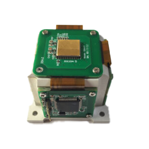
In short, the research on the external measurement method of aircraft rudder deflection angle based on IMU needs to comprehensively consider multiple aspects such as hardware selection, data processing, error analysis and system verification. This measurement method has the advantages of non-contact, real-time, and continuous measurement, and is of great significance for the performance testing of aircraft rudder surfaces and the development of flight control systems. In practical applications, it is necessary to select an appropriate IMU according to specific conditions, optimize data processing algorithms, and take necessary measures to reduce errors. ERICCO's independently developed MEMS IMU can be applied in the field of drones. For example, ER-MIMU-01 can be used for initial alignment in the drone launch system. And has the following characteristics:
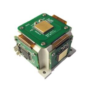
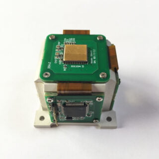
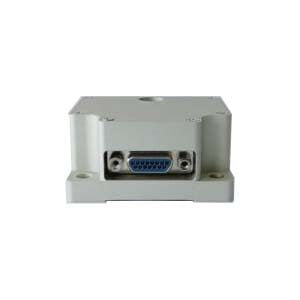
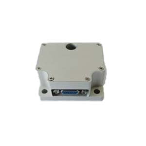
ER-MIMU-01 (0.02 deg/hr)
- 3-axis gyroscope & 3-axis accelerometer;
- Operate Temp:-40℃~ + 80℃;
- Gyro bias instability: 0.02 deg/hr.
If you want to purchase, please contact our relevant personnel.
More Technical Questions
1.IMU working principle & Tactical grade IMU product recommendations
2.Choosing an IMU: FOG IMUs vs MEMS IMUs
3.Application of IMU in the Field of Drones
5.What is the Difference Between IMU and AHRS?
Products in Article
 North-Seeking MEMS IMU