With the development of MEMS technology, the size, power consumption, and cost of inertial sensors are gradually reduced, allowing navigation systems to be designed based on small, low-power, and low-cost inertial sensors. Although there are obvious sensor errors in MEMS-based inertial navigation systems, resulting in relatively poor navigation performance, there are clear restrictions on IMU size, gravity and cost for various products, so the completion of using MEMS IMUs is The needs for various navigation tasks are still very urgent. However, in the absence of external observations, it is impossible to directly apply rotation modulation technology to low-cost MEMS IMUs and transform them into high-performance, low-noise gyroscopes. This is due to the fact that 1/f noise heavily overlaps with the useful signal frequency band. To this end, Yang et al., Qian et al., and Sun and Wang et al. published articles in 2005, 2010, and 2012 respectively, which deduced in detail the impact of RM on the sensor constant zero bias under ideal conditions. Xueyun Wang showed in an article published in 2013 that MEMS sensors have the disadvantages of significant errors and poor error repeatability, making it difficult to apply in complex environments. To address this issue, the impact of RM on navigation performance and different rotation schemes are analyzed. An INS based on RM technology with application of MEMS was developed. In an article published by Wei Sun et al. in 2013, they introduced a method of using a MEMS-based rotating strapdown inertial navigation system so that the sensor bias can be effectively compensated by the rotating IMU. The reciprocating rotation scheme can effectively improve the observability of the system, so it can effectively estimate the constant zero bias of the gyroscope in the horizontal direction and the accelerometer.
The research methods of rotating MEMS IMU mainly include the following aspects:
1.Error analysis and compensation: The error of MEMS IMU is a key factor affecting its performance. Errors can be divided into static errors, dynamic errors and random errors. Static errors and dynamic errors are usually deterministic errors caused by linear and angular motion of the carrier, which can be eliminated by establishing corresponding mathematical models. But for MEMS IMU, it is difficult to establish an error model that satisfies various working environments. Therefore, studying how to effectively compensate for these errors is the key to improving the performance of MEMS IMU.
2.Data collection and processing: In the research of MEMS IMU, data collection and processing are a very important part. The full temperature test cycle can be reduced by designing a specific rotation stage (such as a 45° tilted rotation stage) to simultaneously collect temperature data from the accelerometer and gyroscope. The collected data needs to be processed, including filtering, calibration and other steps, to obtain more accurate results.
3.Calibration method: For the three-axis non-orthogonal errors of the accelerometer and gyroscope in MEMS IMU, the error matrix method can be introduced for calibration. By collecting the flat and rotating data of the six faces of the IMU on a standard horizontal turntable, and then calculating it with the ideal orthogonal matrix, the installation error matrix of each sensor is obtained. For temperature drift errors, polynomial fitting can be used to identify model parameters.
4.Communication and data processing: MEMS IMU data needs to be transmitted and processed through a certain communication protocol. The CAN bus can be used as the information exchange channel between the host computer and the IMU to communicate through a customized communication protocol. On the PC side, software such as Labview can be used for data collection, processing, display and program control to realize the automated operation of the entire calibration system.
Summarize
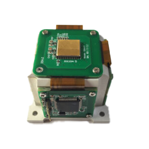
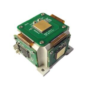
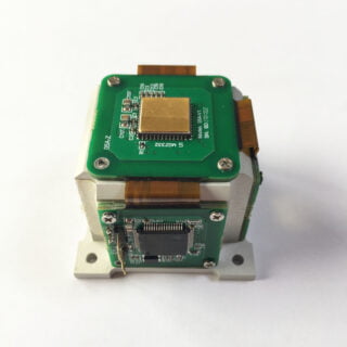
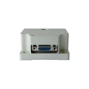
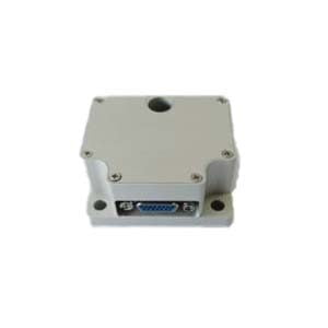
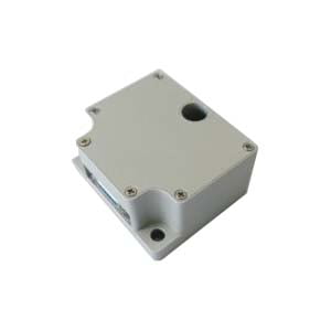
The above aspects are the main methods of rotation-based MEMS IMU research. Through these methods, the accuracy and stability of MEMS IMU can be improved to meet the needs of various application scenarios. As for the accuracy and stability of MEMS IMUs, ERICCO’s MEMS IMUs such as ER-MIMU-01 and ER-MIMU-03 are navigation-grade and have relatively high accuracy. The built-in gyro bias instability is about 0.02 deg/hr. It can be used for north seeking in logging tools/gyro tools, pointing, steering and guidance in advanced mining/drilling equipment, etc. The latter is of tactical grade, with built-in gyro bias instability <0.3 deg/hr, and can be used in robot control and orientation in autonomous machines and unmanned vehicles.
If you want to purchase our products, please click the email address below to contact us.
More Technical Questions
1.IMU working principle & Tactical grade IMU product recommendations
2.Choosing an IMU: FOG IMUs vs MEMS IMUs
3.Application of IMU in the Field of Drones
5.What is the Difference Between IMU and AHRS?
Products in Article