Inertial measurement unit (IMU) is the key of position and attitude system to obtain high-precision position and attitude information and realize high-precision airborne Earth observation. IMU with high-precision fiber optic gyro (FOG IMU) is sensitive to magnetic field due to Faraday effect of fiber coil, and the performance parameters of FOG zero bias and drift are deteriorated, thus the performance of IMU decreases. For FOG without taking any measures, its zero bias sensitivity is 104 (°)/(h·T), which can meet the requirements of general low-precision inertial measurement systems, but typical high-precision inertial navigation systems (such as POS) require FOG zero bias sensitivity of 1 ~ 10 (°)/(h·T), because of this, To achieve high precision IMU with FOG, some technical measures must be taken to reduce the magnetic sensitivity of FOG.
1. Methods to reduce magnetic sensitivity
In the development stage of FOG, the technical measures to reduce magnetic sensitivity are mainly depolarization technology and advanced loop winding technology. Single-mode fiber can achieve lower magnetic field sensitivity than the polarization-preserving FOG through depolarization technology. The polarization-preserving gyro can suppress zero drift well because of its large linear bifold beam relative to the circular bifold beam induced by magnetic field. However, the main axis of polarization-preserving optical fiber has slow rotation in the drawing process, and it will also lead to torsion when winding optical fiber coil. Therefore, the Faraday effect in polarization-maintaining fiber is not completely zero. Using advanced winding technology to reduce the residual torsion of the coil and effectively control the tensioning force during the winding process, it can improve the quality of the polarity-maintaining coil and reduce the magnetic sensitivity. In addition, multiple compensators can be configured in the FOG scheme, the combined magnetic sensitivity of the compensators can be used to eliminate the magnetic sensitivity of the coil, and the FOG magnetic sensitivity can be reduced by using a new type of optical fiber with less magnetic sensitivity.
At the application level, the technical measures to reduce FOG magnetic sensitivity are mainly compensation and magnetic shielding. Magnetic sensors (such as fluxgate, etc.) are used to determine the FOG's magnetic error model in advance through calibration, and then compensation is carried out according to the model in application. However, it is necessary to arrange multiple sensors to fully understand the FOG's magnetic field condition and add hardware circuits, which makes the system more complicated and affects its reliability. In order to isolate the magnetic field interference in the application environment, the shield with double or multi-layer shield structure is usually designed with μ-alloy material to achieve the maximum attenuation of the external magnetic field, so that although it can achieve better shielding efficiency, it often makes the structure complex, cost and weight increase. In the actual airborne application environment, the IMU based on the high precision FOG (FOG IMU) will be subject to the complex electromagnetic interference generated by the airborne electronic equipment and the shadow of the geomagnetic field, which will seriously affect its operational precision in the actual work process, and it will also be subjected to the external electromagnetic environment in the calibration test. The shadow affects its test precision. In this paper, the magnetic field sensitivity of high precision optical fiber IMU is studied, the mechanism of FOG's magnetic field sensitivity is studied, the shielding effect (SE) of the shield is studied with the help of finite element analysis software, and the shield structure is designed. Three FOGs in IMU were screened, and the effectiveness and practicability of the shielding were verified by experiments.
2. Influencing factors of fiber optic gyroscope drift
2.1 Mechanism of influence of magnetic field on FOG
When linearly polarized light passes through the medium along the direction of magnetization or the direction of applied magnetic field, the phenomenon of rotation of the polarization plane is called magneto-optical Faraday effect. In Sagnac ring fiber interferometer, when there is a longitudinal magnetic field parallel to the coil in the plane of the fiber coil, the phase error Δφ generated by two backward linearly polarized beams is twice the Faraday rotation Angle. In practical applications, because the direction and size of the geomagnetic field and the external interference magnetic field are different, and the fiber torsion is distributed along the fiber. In the process of operation, the random stress changes due to temperature variation and vibration and other factors, and can not maintain a constant value, so the phase error of Faraday effect is not a fixed output bias, but a drift of FOG. For the axial magnetic field perpendicular to the optical fiber coil, the theory of the Faraday effect is zero, but in fact, each turn of the optical fiber ring has a small inclination Angle relative to its sensitive axis, when there is an axial magnetic field, it will produce an axial Faraday effect, which makes the FOG show magnetic sensitivity and produce errors.
2.2 Influence of external environment on fog drift
The IMU was installed on the three-axis turntable, and two sets of IMU output data were obtained at the sampling frequency of 100Hz respectively in the off state and the closed state of the turntable. Figure 1 shows the three FOG drifts (DX, DY and DZ, with a single bit of 102 pulse/s, that is, the number of output pulses of 0.01 s) and their spectra (FS, with a amplitude of MX, MY and MZ, with a single bit of 102 pulse/s, respectively) in IMU during turntable shutdown. Frequency classification is fX, fY and fZ, unit is Hz) and power spectrum (PSD, amplitude classification is PSDX, PSDY and PSDZ, single bit is dB). Figure 2 shows three FOG drifts and their frequency spectrum and power spectrum in the IMU during the closing period of the rotary table. The statistical results of FOG drift are shown in Table 1. When the turntable is closed, the FOG data contains frequency components distributed in the band width of 0 ~ 50 Hz. After the turntable is closed, the FOG drift is 5 ~ 10 times that of the original. Three main interference frequencies, 12.48Hz, 24.96Hz and 37.44Hz, are introduced.

3. Summary
We have to take corresponding technical measures to reduce the magnetic sensitivity of FOG, so as to improve the accuracy of FOG IMU.
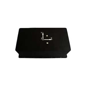
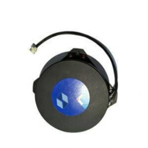
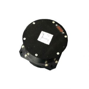
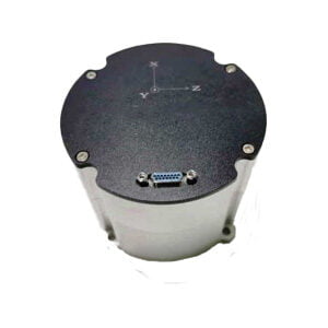
Ericco's FOG IMU ER-FIMU-50, ER-FIMU-60 and ER-FIMU-70 are all composed of fiber optic gyroscopes. In order to improve the accuracy of FOG IMU, we can completely reduce the magnetic sensitivity of the fiber optic gyroscopes inside them by corresponding technical measures.
More Technical Questions
1.Measurement Error and Calibration of FOG IMU
2.Application of IMU in the Field of Drones
3.Choosing an IMU: FOG IMUs vs MEMS IMUs
4.IMU working principle & Tactical grade IMU product recommendations
5.IMU algorithm: data acquisition & calculation of speed and direction
6.Influence analysis of IMU accuracy on spoofing detection algorithm
Products in Article