1. How to ensure the reliability index of the tilt sensor
For the technical indicators and performance indicators of the tilt sensor, there are usually clear and quantitative index requirements, which can be directly measured and tested when the product leaves the factory. For reliability indicators, it is generally impossible to implement direct measurement and inspection, and it is necessary to carry out reliability design and control of the whole process of product development and production to ensure that the reliability indicators meet the requirements. We mainly discuss the reliability supervision and control, design and evaluation and test of tilt sensor in the development, production and use stage.
2. Reliability design
The development stage of inclinometer sensor can be divided into demonstration stage, scheme stage, development stage and finalize stage. According to the technical requirements of the tilt sensor, the MTBF task value θS of the sensor is determined in the demonstration stage, and the θS is preliminarily demonstrated according to the reliability level of the sensor product.
When the inclinometer sensor is in the project stage, it is necessary to design according to the tactical technical index of the inclination sensor and work out the functional block diagram of the sensor. According to the block diagram of tilt sensor, the internal logic relationship in the block diagram is analyzed, and the reliability block diagram of the newly developed inclination sensor is compiled. According to the reliability block diagram of the inclinometer sensor, the reliability indicators are assigned to each subsystem of the sensor, or the reliability indicators on the technical requirements are weighted, and the results after allocation must meet the reliability indicators of the whole system. After the reliability block diagram is prepared and the reliability index is assigned, the estimated reliability value θP is estimated for the components used in the hardware circuit. According to the obtained θP value, the part of the hardware circuit that affects the reliability of the sensor is designed and changed. At last, the functional block diagram, reliability block diagram, reliability distribution index and reliability predicted results prepared according to the technical requirements of the inclination sensor are reviewed periodically in order to improve the design of the defects that affect the reliability of the sensor. In the reliability design of the tilt sensor, the design needs to be considered as shown in Figure 1.
 2.1 Reliability design of hardware circuit
After the inclinometer sensor enters the development stage, the hardware circuit is designed according to the functional block diagram and reliability block diagram.
In the design of hardware circuit reliability, the aspects that need to be considered are shown in Figure 2.

In the process of hardware circuit design, components are the basis of circuit reliability design. In the actual sensor hardware circuit, due to different environments, load changes and a series of reasons such as the design of the sensor drift fault, therefore, in the actual design of the hardware circuit should be integrated into the margin design, after the completion of the hardware circuit design, before the data transmission, it is required to check the integrity of the components in the hardware circuit to ensure that the sensor is powered on. Correct and intact data transmission between each unit. In addition, limit testing and reasonableness testing are performed on all analog and digital inputs and outputs in the hardware circuit.
2.2 Software program reliability design
In the design of the hardware interface software of the sensor, the failure detection of the external input or output device must be considered first, and when the failure is detected, the software can restore the interface to a certain safe state, and the hardware failure mode involved is also required to be considered. When the sensor transmits data, in order to ensure the authenticity and reliability of the data received by the receiver, the data sent by the sender is required to use a specific format and content, so that the sender and the receiver can use the agreed method for verification. In the process of software design, its reliability design structure is shown in Figure 3.

When the software program of the sensor is written, the first thing to consider is the robustness of the software. In software robustness design: First, the power module of the inclinometer sensor may have intermittent failure at the moment of power supply, so that the inclinometer sensor into a potential unsafe state, in order to avoid this state, it is required that the software safely shut down the sensor when the sensor power supply fails, in addition, the power supply of the inclination sensor may have abnormal fluctuations. Software is also required to handle it; Second, the software design must take into account a self-test when the sensor is powered on, verifying that the sensor system itself is safe and can operate normally, and when necessary, the sensor can carry out periodic self-testing; Third, the inclination sensor needs to work normally in electromagnetic radiation, static interference and other environments, which requires the sensor hardware circuit design to be processed according to the technical requirements, so that the sensor can control the external interference within the specified range, when there is external interference, the software is reset again, so that the sensor can still operate normally. Secondly, it is necessary to carry on the margin design when writing the sensor operation program. While ensuring the storage capacity and data channel transmission capacity of each module of the software, the software margin of the inclination sensor should be planned to ensure that the software margin meets the requirements. According to the specific state of each subsystem during software running, the arrangement of various cycles and working time series of software is determined to ensure that sufficient margin is reserved between software working time series.
Finally, consider the data definition when the sensor program is written. When defining the data in the software operation process, it is necessary to ensure that the defined data must be within a reasonable range, so that the sensor can ensure the size and error of the value within the specified range during the data operation process to ensure the accuracy of the data operation. In addition, reasonableness checks are also carried out at the entrance, exit, and other key locations of the software.
2.3 Structural reliability design
In addition to the protection of the external environmental stress, the electromagnetic compatibility of the inclinometer sensor is mainly optimized in the structure of the sensor. Under modern conditions, electromagnetic interference is everywhere, in this environment to make the sensor normal operation, it is required to optimize the sensor in hardware circuit, overall structure, manufacturing process, etc., in order to reduce the sensitivity of the sensor for interference, so that the external entry and internal leakage of electromagnetic interference can be controlled in a acceptable range.
2.4 Process reliability design
Process reliability design is mainly divided into printed board reliability design, electrical interconnection design and "three defenses" design. The reliability design of the printed circuit board requires the layout of the entire circuit board to be reasonable, and a single functional module or functional circuit is placed on a panel as far as possible, which is more convenient for later troubleshooting and maintenance. The circuit board should be rationally arranged on the circuit board, the circuit at all levels should be arranged and combined according to the distribution of the schematic diagram, the input and output of the sensor should be arranged separately, the analog circuit module and the digital circuit module should be isolated, the layout and wiring should be reasonable as far as possible, and the generation of parasitic coupling electromagnetic interference should be suppressed. When placing electronic components on the circuit printed board, it is required to be as suitable as possible for visual inspection of the entire circuit printed board, to facilitate the inspection of the nominal value of electronic components and fault location. When placing large and heavy components on the circuit printed board, it is necessary to reinforce them to prevent damage to components caused by vibration and impact of the sensor and make the sensor unable to operate normally. The design of electrical interconnection requires the sensor process specification to specify the installation and welding temperature and time of the components, the welding specifications of the inserted components and the operating conditions of the welding operators. The "three defenses" design requires the developer to fully understand the use environment of the sensor, master the characteristics of the sensor use environment and the law of change, analyze the stress conditions of the sensor failure in its use environment, and finally choose the suitable defense for the sensor
Enclosures, materials and sensor manufacturing processes.
3 Summary
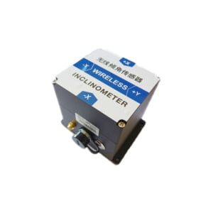
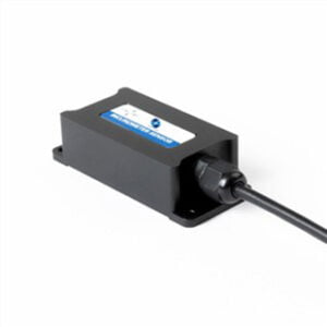
By analyzing the reliability of inclinometer sensors in the process of development, production and use, we integrate the reliability design of wireless ER-TS-12200-Modbus and single-axis ER-TS-3160VO, ER-TS-4150VO and other tilt sensors into the development and production of sensors. Through the reliability information collected by customers during the use of such products, the reliability assessment of the sensor is carried out, and the reliability improvement of the tilt sensor is finally completed.
More Technical Questions
1.Tilt Sensor Automatic Calibration System
2.Research on Angle Control Technology of Tilt Sensor
3.Tilt sensor, Tilt Switch&Other Common Problems in Installation and Use Process
4.Application of Tilt Sensor in Vehicle Four-wheel Positioning
5.Tilt Sensor Use and Maintenance Precautions
6.Influence of Ambient Temperature on Measurement Data of Tilt Sensor
Products in Article