Why introduce tilt sensors to form a closed-loop control system?
How to calibrate the inclinometer sensor and connect it to the coordinated loading control system becomes the key to solve the following problems.
In the traditional structural strength test, the coordinated loading control system mainly controls the load and displacement. Its core control unit belongs to closed-loop negative feedback regulation, and PID control is commonly used in engineering. However, in the loading process of an aircraft structure strength test, it is required to test the performance characteristics of a moving mechanism while the mechanical load is loaded, but the regulator of the mechanism belongs to open loop control, and it cannot be measured effectively and accurately during the loading process. This requires the introduction of inclinometer sensors in the actual loading process to form a closed-loop control system to achieve accurate Angle control. Therefore. In this paper, the signal parameters of tilt sensor are studied and tested, and the calibration method of sensor feedback signal and the method of signal participating in closed-loop control are proposed to realize real-time Angle measurement and control of the moving mechanism of test piece.
1. The way the inclination sensor is connected to the coordinated loading control system
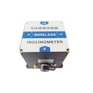
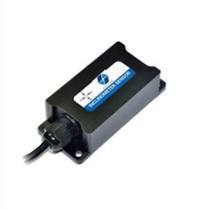
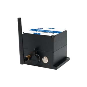
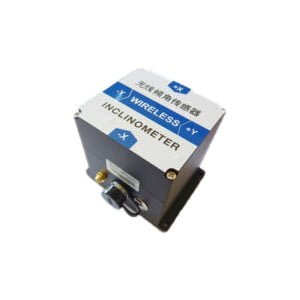
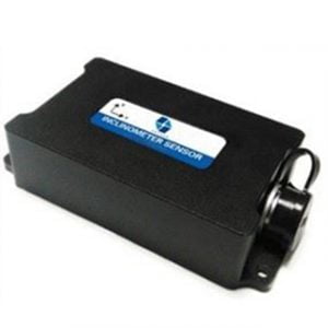
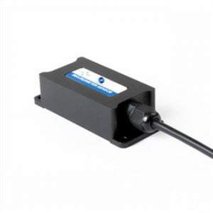
In the strength test of a new type of structure, it is necessary to apply mechanical load while coordinating the loading control system can synchronously monitor the Angle change of the moving mechanism of the test piece, that is, the Angle change between the measuring surface and the horizontal plane. Therefore, the inclination sensor is introduced in the test for the Angle monitoring of the moving mechanism of the test piece. The inclination sensor is shown in Figure 2.

The output signal of the inclination sensor is DC analog signal, which needs external 24V DC excitation power supply in normal operation. The excitation power supply provided by DC voltage regulator power supply is used as the excitation power supply of the inclinometer sensor in the test. After research, there are two ways to connect the output of the inclination sensor to the coordinated loading control system. One is to transform the sensor connection mode of the coordinated loading control system and access it from the sensor channel panel; the other is to use the BNC connector to access it from the analog input channel. We test Angle parameters to participate in closed-loop control, so choose the first access mode. In addition, since the channel input of the control system recognizes the DC voltage signal, the output signal of the inclination sensor needs to be converted before it is connected to the control system. A precise resistor is connected at the output end of the inclination sensor to convert the output signal of the inclination sensor from current signal to voltage signal. The access control system is shown in Figure 2.

2 Calibration method
Since the voltage signal is an analog signal, it is necessary to calibrate the voltage signal after it is connected to the control system, that is, the corresponding relationship between the output voltage value of the inclination sensor and the actual Angle value is determined by adjusting the channel gain, △k, zero point, unit and other parameters, and ensure that the reading result of the control system is consistent with the actual Angle when the actual Angle is changed. There are two ways of calibration, respectively to test it, the process is as follows.
2. 1 Zero gain method
Firstly, a precision resistor with a fixed resistance value of 200Ω is connected at both ends of the output signal line of the inclination sensor, so that the DC current signal output by the inclination sensor becomes the DC voltage signal that the control system can recognize. The signal output range of the inclinometer sensor is: 4 ~ 20 mA, and the corresponding voltage signal range is: 0.8 ~ 4 V. The maximum voltage range allowed by the coordinated loading control system is -10 ~ 10 V. The signal gain of the input channel can be calculated according to the following formula.

Input this gain into the analog signal channel, and then place the inclination sensor horizontally. Refer to the following table to obtain the current value corresponding to the output of the inclination sensor when it is placed horizontally, and then convert it to the voltage value. Then adjust the zero point to make the voltage displayed by the control system this voltage value.

2. 2 Calculate the channel method
The Angle θ of the inclinometer sensor and the X axis output x are linear, that is, θ = k × x + b
Referring to the specific values in the table above, the least square method can be used to determine the linear relationship between the Angle θ(°) and the X-axis output x(mA), that is, to determine the k and b values. As with the gain method, a precision resistor with a fixed resistance value of 200Ω is connected at both ends of the output signal line of the inclinometer sensor, so that the DC current signal output by the inclination sensor becomes the DC voltage signal that the control system can recognize. Finally, the voltage feedback signal V of the inclination sensor monitored by the control channel is assigned to a calculation channel, and the corresponding Angle value can be obtained by editing the voltage feedback signal of the control channel into the following formula through the formula editor module of the calculation channel:
![]()
When the unit of the computing channel is set as the Angle, the real-time monitoring of the Angle can be realized through the computing channel. The zero gain method and the calculation channel method are used to calibrate the two inclination sensors respectively, and the results are consistent with the actual Angle, which proves that the two calibration methods are feasible.
3. Test and verification
In the strength test of a new type structure, the deflection Angle of the moving airfoil is measured and controlled by introducing an inclination sensor.
3. 1 Test system construction
The inclination sensor is attached to the active airfoil, and the output axis X axis is perpendicular to the deflection direction of the active airfoil, which is used to measure the deflection Angle of the active airfoil relative to the horizontal plane. The measurement signal is connected to the coordinated loading control system through either of the above two access methods. The inclinometer sensor is pasted as shown in Figure 2.
The Angle deflection of the movable airfoil is driven by the rotation of the steering wheel and the deflection of the movable airfoil through the hydraulic swing cylinder installed in the cockpit. The hydraulic swinging cylinder is fixed to the driving disc, and a torque sensor is installed between the two to monitor the torque during the rotation of the driving disc driven by the swinging cylinder; The rear end of the hydraulic swing cylinder is connected with an angular displacement sensor to measure the rotation Angle of the steering wheel in real time. The signals of the torque sensor and the angular displacement sensor are simultaneously connected to the coordinated loading control system for monitoring or control, and the output control signal of the control system controls the opening size of the servo valve to achieve accurate control of the deflection Angle of the movable airfoil.
Should note:
① The angular displacement sensor and the hydraulic swing cylinder are fixed connected, and the rotating shaft has no relative rotation;
② The rotation axis of the angular displacement sensor, hydraulic swing cylinder and torque sensor should be in the same straight line and remain level on the horizontal plane.
3. 2 Test Method
Coordinated loading control system, hydraulic swing cylinder and angular displacement sensor constitute closed-loop control. The command given by the control system is the rotation Angle command of the steering wheel, and the control cylinder drives the steering wheel to rotate, so as to realize the Angle deflection of the movable airfoil; The inclinometer sensor only acts as the Angle measurement and monitoring of the active airfoil, and calculates and monitors the Angle of the active airfoil in real time through the computing channel.
3. 3 Test results and analysis
The test adopts method one to control loading, the results show that the Angle control can be realized, and the control accuracy meets the requirements of the test. The angular deflection results of the movable airfoil are shown in Figure 3.

4 Summary
The technique has been successfully verified in the control test of a certain type of aircraft elevator (rudder surface with load). Ericco's ER-TS-3160VO and ER-TS-4158CU are two hot-selling tilt sensors of voltage and current type. They can access the control system from the sensor channel panel by modifying the sensor wiring mode of the coordinated loading control system. Because the input end of the control system's channel recognizes DC voltage signals, Therefore, before the sensor output signal is connected to the control system, the output signal needs to be converted. A precise resistor is connected at the output end to convert the output signal from current signal to voltage signal. By using the test system, the deflection degree of the moving airfoil is controlled while the mechanical load is applied to the moving airfoil. The test system can be further improved and optimized, so that the control quality is higher and the application range is wider.
More Technical Questions
1.Function and Test Analysis of Tilt Sensor Detection System
2.The Advantages and Disadvantages of the Transmission Mode of Tilt Sensor
3.Why are Tilt Sensors Important?
4.What is the Difference between Single, Double, Three axis in Tilt Sensor
5.What are the Advantages of Tilt Sensor
6.Is Tilt Sensor Analog or Digital?
Products in Article