1. Tilt sensor calibration method
Tilt sensor is widely used in the field of engineering measurement, and its measurement accuracy is often related to the evaluation of the deformation of structures, which is of great significance to the construction quality control and safety production management of construction engineering site. The manual two-point calibration method is commonly used to calibrate the inclinometer sensor, which describes the relationship between the output voltage and the Angle through a straight line, and is usually only suitable for the inclination sensor with low accuracy requirements. If the sensor has relatively high accuracy requirements, it is necessary to use a higher precision inclination chip and calibration method. Multi-point calibration is an effective calibration method to improve the accuracy of sensors, but in the case of a large number of fixed points using manual trigger, reading and calculation calibration method, not only low efficiency, and by human factors interference, is not conducive to the large-scale production of sensors. By designing an automatic calibration system for tilt sensor based on programmable electric Angle station, we realize the automatic change of Angle, reading and result output in the calibration process of inclinometer sensor, improve the calibration efficiency and sensor accuracy, and reduce the dependence of the calibration process on the technical level and experience of the operator.
2. Principle of automatic calibration of inclination sensor
The calibration of the sensor means that the measured value of the inclinometer sensor with higher precision is input to the inclination sensor to be calibrated as the standard value, and the feedback value of the sensor to be calibrated is obtained for data fitting processing. The common calibration method only calibrates the inclination sensor by two fixed points, and describes the error Angle relationship of the sensor by a straight line. This method is easy to operate and is suitable for tilt sensors with low precision.
However, if the inclinometer sensor with a measuring range of -15°~+15° collects data every 1°, and the error of each Angle is obtained as shown in Figure 1, it can be found that the error of the sensor is not linear with the Angle when the Y-axis interval is set to 0.01°. Therefore, if the sensor is calibrated by multi-point calibration method, the error of the sensor is not linear with the Angle. The accuracy of the sensor can be further improved by fitting a curve to describe the error characteristics of the sensor.

Therefore, this paper adopts the multi-point calibration method that sets 1 fixed point every 1°, and the third-order fitting method based on the principle of least squares to compensate the sensor error. The error fitting model is as follows:
Δφ = a1x3 + a2 x 2 + a3x + a4 (1)
In the formula, Δφ is the error value of the inclination Angle, x is the acquired value of the sensor to be calibrated, and a1, a2, a3 and a4 are the coefficients of the fitting polynomial.
3.Overall system scheme
The automatic calibration system is composed of three parts: electric Angle station, standard inclination sensor and PC calibration software, as shown in Figure 2.

During calibration, the tilt sensor to be calibrated and the standard value sensor are fixed parallel to the electric Angle platform, the electric Angle platform is connected to the PC calibration software using RS485, and the tilt sensor to be calibrated and the standard value sensor are connected to the PC calibration software through the RS232 of the lora module at the receiving end. The calibration software at the PC end sets the Angle of the fixed point, the calibration software automatically controls the electric Angle station to find the corresponding fixed point, and continuously collects data at each fixed point to analyze whether the Angle data of the tilt sensor and the standard value sensor to be calibrated is stable (the difference between the last 10 sets of data collected does not exceed 0.003°). Record the readings of the tilt sensor and the standard value sensor to be calibrated, and automatically rotate to the next set point until all 31 set points are collected, and the software automatically calculates each parameter of the fitted curve according to the collected data.
4. System testing and analysis
4.1 Functional Testing
In order to verify the function of the automatic calibration system, an inclination sensor with a factory accuracy of 0.1° was placed in the system for calibration. The resulting data are shown in Table 2.

It can be seen from Table 2 that before calibration, the maximum error of the sensor X axis is -0.037°, and the maximum error of the Y axis is 0.031°. The error fitting curve of the sensor calculated by the calibration software is shown in Figure 6.

4.2 Accuracy Verification
In order to verify the accuracy of the calibrated sensor, the automatically calibrated inclination sensor is sent to a professional measuring institution for measurement. The measurement accuracy is required to be 0.01°, and the measurement data are shown in Table 3.

The measurement results show that the maximum error of X axis and Y axis is 0.006° and 0.009°, respectively, satisfying the accuracy index of 0.01°. The accuracy of the sensor is improved by one order of magnitude after calibration by the automatic calibration system.
5.Conclusions
We demonstrate the design direction of an automatic calibration system for inclinometer sensor, and carry out the calibration and performance test of the system. During the design and implementation of the automatic calibration system, the following conclusions are obtained:
(1) The automatic calibration system based on the programmable electric Angle station can realize the automatic calibration of the inclinometer sensor, effectively improve the calibration efficiency and save labor costs.
(2) The selection of the resolution of the electric Angle station should fully consider the mechanical structure characteristics of the Angle station. Compared with the resolution of 0.007° and 0.00036°, the resolution of 0.0007° can ensure the calibration accuracy while having higher calibration efficiency. The resolution of the ER-TS-12200-Modbus is 0.0005°, and the resolution of the ER-TS-22800 is 0.0008°, so the ER-TS-22800 can achieve higher calibration efficiency while ensuring calibration accuracy.
(3) The experimental results show that compared with the traditional two-point calibration method, using the multi-point calibration method to calibrate the inclinometer sensor and using the third-order curve to fit the error characteristics of the sensor can effectively improve the accuracy of the inclinometer sensor.
More Technical Questions
1.Research on Angle Control Technology of Tilt Sensor
2.Research on Temperature Characteristics of Tilt Sensor
3.Tilt sensor, Tilt Switch&Other Common Problems in Installation and Use Process
4.Application of Tilt Sensor in Vehicle Four-wheel Positioning
5.Tilt Sensor Use and Maintenance Precautions
6.Influence of Ambient Temperature on Measurement Data of Tilt Sensor
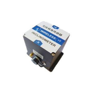
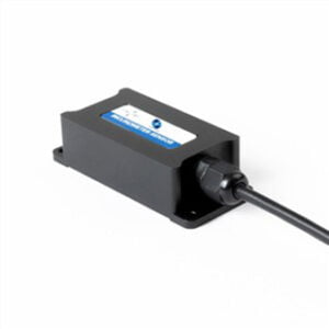
Products in Article