1. Methods to improve the accuracy of tilt sensor
As a very important physical quantity, Angle has a very important position in various fields such as industry, military and aviation, so its measurement is extremely important, and Angle measurement is an important part of metrology science. Tilt sensor is a device to measure the inclination Angle, it is an important link to realize the inclination measurement and automatic control, and its accurate and high-precision measurement becomes the most important thing, so it is necessary to study the algorithm to improve the measurement accuracy.
The research and implementation of the algorithm to improve the accuracy of the tilt sensor are obtained on the basis of practice. The method is based on the arcsine Angle output principle of the tilt sensor. Through repeated data processing and comparison of the old and new error values in the test, the appropriate correlation coefficient is finally obtained, so as to improve the accuracy.
2. Measurement preparation
Measuring the accuracy of biaxial tilt sensor is mainly divided into several steps: making test circuit board, compiling program, building test platform, data acquisition, data analysis and calculation. First of all, it is necessary to make a test circuit board, which is mainly made of dual-axis tilt sensor, single-chip microcomputer, analog-digital converter, MAX232 and other related components.
When the test circuit board is made, it is necessary to use the burner and related software to burn the test program in the single chip microcomputer, as shown in Figure 1. The test circuit board with sensor is fixed on the three-axis turntable, and the circuit board is connected to the computer that collects data, so as to form a complete test device, as shown in Figure 2.


3. Measurement process
After the preparation work is completed, the measurement begins. Along with the rotation of the central axis and the internal axis of the three-axis turntable, the two-axis tilt sensor has the corresponding output value. We collect the data and save it on the computer. After that, the output value is processed, and the output value after data processing is compared with the rotation Angle of the turntable to calculate the accuracy of the sensor. Because the data processing of the central axis and the internal axis is the same, the central axis is introduced here as an example. After many calculations and measurements, the most suitable coefficient is selected to meet the requirements of high precision.
Since the measurement range of the biaxial tilt sensor we selected is between -30℃ and +30℃, here we set the minimum Angle of rotation of the turntable to 5°. Rotation Angle are respectively - 30 °, 25 °, and 20 °, 15 °, and 10 °, 5 °, 0 °, + 5 °, + 10 °, + 15 °, + 20 °, 25 °, 30 ° +, will these values are expressed in Ai. Each time the turntable is rotated, the output value of the sensor is recorded by relevant software, as shown in Figure 3. Among the many output values each time, the minimum and maximum values are recorded, and the data is saved to the computer, as shown in Table 1.

Taking the data at 0° as the benchmark, the output values Ci, Di, Ei and the difference between each output value and the set value Ai Cj, Dj, Ej were calculated using the corresponding formulas

The calculated data table is shown in Table 2.

Curve fitting was performed on Cj, Dj and Ej, as shown in Figure 4.

According to the value 1026 corresponding to 0°, the output value is converted into an Angle, the evaluation test and multiple measurements are carried out. Finally, the optimal values 1028 and 1639 are selected, and the output values Ci, Di, Ei and the difference between each output value and the set value Ai Cj, Dj, Ej are calculated by using the corresponding formulas.

The calculated data table is shown in Table 3. Curve fitting was performed on Cj, Dj and Ej, as shown in Figure 5.

4 Summary
Through measurement and data processing, the requirements for improved accuracy are finally met. As can be seen from Figure 5, the measurement error of the biaxial inclinometer sensor has reached (-0.15~+0.17). To meet higher requirements, the algorithm needs to be further improved.

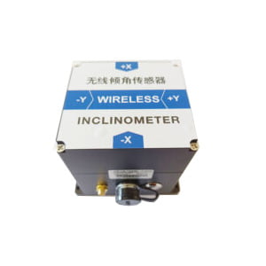
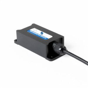
For our biaxial inclinometer sensors, such as ER-TS-4250VO and ER-TS-4258CU, we can obtain the appropriate correlation coefficient by repeated data processing and comparing the old and new error values in the test through the above algorithm, so as to improve the measurement accuracy of the sensor.
More Technical Questions
1.Analysis of Influencing Factors of Measurement Error of Tilt Sensor
2.How to Compensate Temperature of Tilt sensor
3.Stability Test and Analysis of Tilt Sensor
4.How to Improve Reliability of Tilt Sensors
5.Tilt Sensor Automatic Calibration System
6.Research on Angle Control Technology of Tilt Sensor
Products in Article