Fluxgate directional assembly are composed of accelerometer sensors and fluxgate sensors, which are mainly used in directional drilling, petroleum industry and other fields to measure borehole inclination, azimuth angle and tool face angle. Directional drilling in the petroleum industry began in the late 19th century, when rotary drilling technology was introduced to replace the old ton drill drilling, without considering the problem of stabilizing the drill string to control the trajectory of the hole. However, borehole measurements showed that the early "vertical" boreholes were far from "vertical". In both vertical and directional drilling, it is necessary to determine the location of the borehole below the surface. This requires the use of measuring instruments that can measure inclination and azimuth along the wellbore at different depths. The position of the hole relative to the surface can be calculated from the accumulated measurement results.
In this paper, the structure and working principle of fluxgate directional assembly will be introduced, and the main measuring borehole inclination angle, tool face angle and azimuth angle will be introduced.
Structure and working principle of fluxgate directional assembly
1. Acceleration sensor
The acceleration sensor adopts magnetic-liquid suspension gravity acceleration sensor, which has the characteristics of strong impact resistance and small size, and its accuracy is about ± 0.1%. The structure is shown in Figure 1.
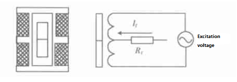
Figure 1 Structure and working principle of acceleration sensor
The gravity acceleration sensor is mainly composed of two winding king frame, cylindrical magnetic steel and suspension magnetic steel magnetic fluid. The magnetic steel is placed into the axle hole of the king frame, and the axle hole is filled with magnetic liquid. When there is no external acceleration, the magnetic steel is in the mechanical 0 position, the inductance of the two windings is the same, and its output is 0. When the acceleration acts on the axis of the magnetic steel, the displacement of the magnetic steel causes the inductance of the two windings to increase and decrease, and the unbalanced voltage appears on the sensor. After the band-pass amplification, phase-sensitive detection and filtering, the feedback current If is input to the two windings in the acceleration sensor through the feedback resistance Rf, and an electromagnetic force opposite to the gravitational acceleration is generated to prevent the magnetic steel from shifting. The following relationship is established:
ma=KIf
If=ma/K
Where, a inputs the axial acceleration; m is the quality of magnetic steel; K is the electromagnetic force coefficient. The voltage at both ends of the feedback resistance Rf is:
Uf=RfIf
The size of Uf directly reflects the magnitude of the gravitational acceleration subject to the acceleration sensor, and its direction is related to the phase of the output waveform of the acceleration sensor, and this value can be sent to the following circuit for processing.
2. Fluxgate sensor
There are many varieties of fluxgate sensors, but the working principle is basically the same. The common fluxgate sensor is to install two windings on a closed high permeability material, and the two windings form a bridge with the secondary side of the excitation transformer. When the external magnetic field is perpendicular to its input axis, the fluxgate output is 0; When the external magnetic field is not perpendicular to the input axis of the fluxgate, the state of the magnetic core changes, and the external magnetic field and the excitation on one side of the magnetic core are superimposed, and the saturation increases, and the external magnetic field and the excitation on the other side of the magnetic core are reduced, and the saturation decreases. When the magnetic field alternates and the magnetic core enters the linear segment from the saturated region, the pulse voltage of different sizes is induced on the two windings, and its amplitude is related to the external magnetic field and the frequency is 2 times of the excitation frequency. The output of the fluxgate is amplified by bandpass, phase sensitive detection and filtering to form a DC voltage, which provides feedback current to the two windings of the fluxgate through the feedback resistance, and the generated magnetic field is offset with the external magnetic field, so that the fluxgate always works in a state without static error, so that the fluxgate has a high linearity. The working principle of fluxgate is shown in Figure 2.
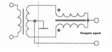
Figure 2. Working principle of fluxgate
Measurement content of fluxgate directional assembly
1. Well inclination
As shown in Figure 3, in the right triangle inside the vertical plane, the inclination Angle is the Angle from the vertical line to the Z-axis (accelerometer axis). The inclination Angle α can be obtained by the following formula:
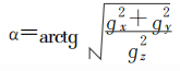
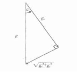
Figure 3. Well inclination
2. Tool face Angle
Tool face Angle is a quantity to locate the travel direction of the drill tool in directional drilling, which is divided into gravity tool face and magnetic tool face. When the well Angle is very small, the gravity tool face Angle cannot be measured, so the magnetic tool face Angle should be used. Gravity tool face Angle θg is the Angle between the high side determined by the gravity vector and the X-axis (accelerometer axis) when looking down the hole, as shown in Figure 4. This Angle can be obtained by the following formula:
tgθg=gx/gy
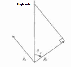
Figure 4 Tool face Angle
The magnetic tool surface Angle θM is the Angle between the magnetic North Pole and the y axis. When the well inclination is less than a certain value, the gravity tool face Angle cannot be accurately measured, even if measured, it is extremely inaccurate. Therefore, when the inclination Angle is less than a certain value, the magnetic tool face Angle is used, that is:
tgθM=Hx/Hy
3. Azimuth Angle
The square Angle is the Angle rotated clockwise from the North Pole to the z axis in the horizontal plane. To calculate the well azimuthing, the fluxgate and accelerometer readings must be decomposed into two axes, as shown in Figure 5. Axis V1 is the projection of the borehole direction in the horizontal plane. Axis V1 and axis V2 are perpendicular, so the azimuth Angle β can be obtained by the following formula:
tgβ=V2 component value /V1 component value
Azimuth β=arctg(V1/V2)
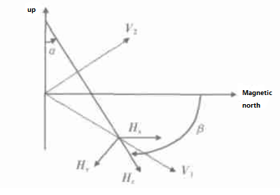
Figure 5 Azimuth Angle
Conclusion
Acceleration sensors measure the gravitational field component of the Earth, while fluxgates measure the magnetic field component of the Earth. The ER-DOS-03 is a dynamically measured fluxgate directional assembly that can operate at 150 ° C, while the ER-OS-05 is a static measurement operating at 125 ° C.
If you are interested in fluxgate directional assembly, please contact us.
More Technical Questions
1.Fluxgate Directional Assembly: The Working Principle of Fluxgate
2.How Do Fluxgate Directional Assembly work in MWD
3.Application of Fluxgate In Fluxgate Directional Assembly
4.The Accelerometer And Fluxgate In The Fluxgate Directional Assembly
5.Sensor Calibration In Fluxgate Directional Assembly
6.Design of fluxgate directional assembly
Products in Article

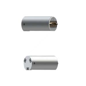
Dynamic Fluxgate Directional Assembly

 Economical Fluxgate Directional Assembly
 High Temperature Fluxgate Directional Assembly