

Definition of micromachines
Micro-mechanical MEMS is the abbreviation of Micro Electro Mechanical systems in English, namely, Micro-electromechanical systems. Micro-electro-mechanical system (MEMS) technology is a cutting-edge technology in the 21st century based on micro/nanotechnology. It refers to the technology of designing, processing, manufacturing, measuring and controlling micro/nano materials. It can integrate mechanical components, optical systems, drive components and electronic control systems into a whole unit of micro system. This micro-electro-mechanical system can not only collect, process and send information or instructions, but also act independently or according to external instructions according to the acquired information. It uses the manufacturing process of combining microelectronics technology and micromachining technology (including silicon body micromachining, silicon surface micromachining, LIGA and wafer bonding technology) to manufacture various kinds of sensors, actuators, drivers and microsystems with excellent performance, low price and miniaturization. Micro-electro-mechanical system (MEMS) is a new interdisciplinary technology developed in recent years, which will have a revolutionary impact on human life in the future. It involves machinery, electronics, chemistry, physics, optics, biology, materials and other disciplines.
Working principle of MEMS gyroscope
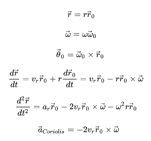
Traditional gyroscopes mainly use the principle of conservation of angular momentum, so it is mainly a rotating object, and its rotation axis direction does not change with the rotation of the support bearing it. But the working principle of micromechanical gyroscope is not the same, because it is not easy to use micromechanical technology to process a rotatable structure on the silicon substrate. The micromechanical gyroscope uses the Coriolis force - the tangential force of a rotating object in radial motion. The following is the method to derive the Coriolis force. It should not be difficult for readers with mechanical knowledge to understand.
Set up a dynamic coordinate system in space (Figure 1). Using the following equation to calculate the acceleration, three terms can be obtained, which are from radial acceleration, Coriolis acceleration and tangential acceleration.
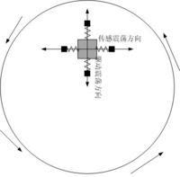
Figure 1
If there is no radial motion of the object on the disk, the Coriolis force will not be generated. Therefore, in the design of MEMS gyroscopes, this object is driven to move radially or vibrate back and forth, and the corresponding Coriolis force is constantly changing back and forth in the horizontal direction, which may cause the object to vibrate slightly in the horizontal direction, and the phase is exactly 90 degrees different from the driving force. (Figure 2) MEMS gyroscopes usually have removable capacitor plates in two directions. The radial capacitance plate plus the oscillating voltage forces the object to move radially (a bit like the self-test mode in the accelerometer), and the lateral capacitance plate measures the capacitance change caused by the lateral Coriolis motion (like the accelerometer measuring the acceleration). Because the Coriolis force is proportional to the angular velocity, the angular velocity can be calculated from the change of capacitance.
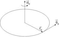
Figure 2
Structure
The design and working principles of micromechanical gyroscopes may be various, but the open micromechanical gyroscopes all adopt the concept of sensing angular velocity of vibrating objects. The micromechanical gyroscope designed by using vibration to induce and detect Coriolis force has no rotating parts and no bearing, which has been proved to be capable of mass production using micromachining technology.
Most micromechanical gyroscopes rely on alternating Coriolis forces caused by orthogonal vibration and rotation. The vibrating object is suspended on the base by soft elastic structure. The whole dynamic system is a two-dimensional elastic damping system, in which the Coriolis force induced by vibration and rotation transfers the energy proportional to the angular velocity to the sensing mode.
Through improved design and electrostatic debugging, the resonance frequency of drive and sensor is consistent, so as to achieve the maximum possible energy transfer and achieve the maximum sensitivity. Most micromechanical gyroscopes are completely or nearly matched in driving and sensing modes. They are extremely sensitive to changes in the vibration parameters of the system, and these system parameters will change the natural frequency of vibration. Therefore, a good control architecture is needed to make corrections. If high quality factor (Q) is required, the bandwidth of drive and induction must be very narrow. Increasing the bandwidth by 1% may reduce the signal output by 20%.
Performance parameter
Important parameters of MEMS gyroscope include resolution, zero angular velocity output, sensitivity and measurement range. These parameters are important indicators to judge the performance of MEMS gyroscope, and also determine the application environment of gyroscope.
Resolution refers to the minimum angular velocity that the gyroscope can detect. This parameter and zero angular velocity output are actually determined by the white noise of the gyroscope. These three parameters mainly show the internal performance and anti-interference ability of the gyroscope. For users, sensitivity is more practical. The measuring range refers to the maximum angular velocity that the gyroscope can measure. Different applications have different requirements for various performance indicators of gyroscope.
Single-double difference
New product group of single-axis and dual-axis MEMS angular velocity sensors (gyro sensors). This series is mainly used for game consoles, input devices, navigators, PND (Portable Navigation Device) and digital cameras.
Single axis products can detect the yaw direction. Dual-axis products are available with varieties that can detect the pitch direction and roll direction, as well as varieties that can detect the pitch direction and yaw direction. The detectable angular velocity varies from variety to variety, with a maximum of 30-6000 degrees per second. The output is an analog signal. Each product is equipped with two ports for outputting (without amplification) and amplifying the signal of each axis to 4 times. The temperature error and the error changing with time are reduced. The zero temperature shift is 0.05 degrees/second/℃. In terms of noise, the varieties with detectable angular velocity of 30 degrees per second are controlled at 0.014 degrees per second/√ Hz.
The power supply voltage range is+2.7~3.6V. 5mm for packaging × 5mm × 1.5mm 16-terminal LGA. The operating temperature range is - 40~+85 ℃.
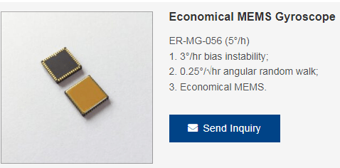
Let's take a look at Ericco's several popular single-axis and dual-axis MEMS gyroscopes.
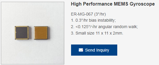
Single-axis MEMS gyroscopes
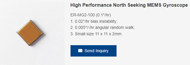
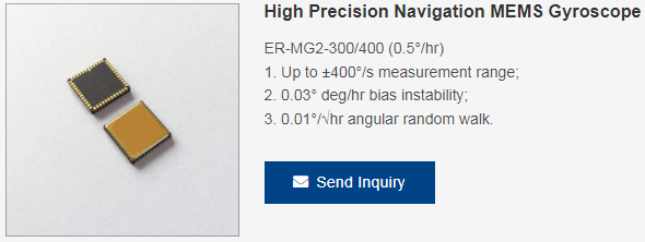
Dual-axis MEMS gyroscopes
Development overview
According to the domestic literature in recent years, the gyroscopes in the application research of inertial navigation in China can be roughly divided into three categories according to their structure: mechanical gyroscopes, optical gyroscopes, and micromechanical gyroscopes. Mechanical gyroscope is an angle sensor that measures the correct orientation of the carrier by using the stability of the rotating shaft of the high-speed rotor. Since it was first used in the shipborne north pointing gyrocompass in 1910, many kinds of mechanical gyroscopes have been explored. The liquid-floated gyroscope, dynamically tuned gyroscope and electrostatic gyroscope are three kinds of rigid rotor gyroscopes with mature technology. The accuracy is in the range of 10E-6 degrees/hour to 10E-4 degrees/hour, reaching the high technical level in the field of precision instruments. In 1965, China's Tsinghua University first began to develop electrostatic gyroscope, with the application background of "high-precision marine INS". In 1967-1990, Tsinghua University, Changzhou Navigation Instrument Factory, Shanghai Jiaotong University and others jointly developed and successfully developed the engineering prototype of electrostatic gyroscope. The bias drift error is less than 0.5 °/h, and the random drift error is less than 0.001 °/h. China, the United States and Russia have become the countries that master electrostatic gyroscope technology in the world. With the development of optoelectronic technology, laser gyro and fiber optic gyro came into being. Compared with laser gyroscope, fiber optic gyroscope has lower cost and is more suitable for mass production. The research of FOG in China started late, but has made many gratifying achievements. Aerospace Science and Technology Group, Aerospace Science and Technology Group, Zhejiang University, Northern Jiaotong University, Beihang University and other institutions have successively carried out the research of fiber optic gyroscope. According to the information available, the development accuracy of domestic FOG has reached the requirements of low and medium accuracy of inertial navigation system, and some technologies have even reached the level of similar foreign products. Since the 20th century, with the development of electronic technology and micromachining technology, MEMS gyroscope has become a reality. Since the 1990s, MEMS gyroscope has been widely used in civil products, some of which are used in high-precision inertial navigation products. The research of MEMS gyroscope in China began in 1989, and has developed hundreds of micron-size electrostatic motors and 3mm piezoelectric motors. The gyro technology of the navigation and control teaching and research group of Tsinghua University is very mature, and has mastered the micromechanical and optical waveguide gyro technology. Now it has made a miniature gyroscope prototype and obtained some data. The Scientific Research Center of the Department of Precision Instruments and Machinery of Southeast University has also continued to develop and research key components, micromechanical gyroscopes, new inertial devices and GPS integrated navigation systems, meeting the needs of the dual-use market. In short, with the development of science and technology, compared with the high cost of electrostatic gyroscope, the precision of fiber optic gyroscope and micromechanical gyroscope with lower cost is getting higher and higher, which is the general trend of the development of gyroscope technology in the future.
Application
The micromechanical gyroscope is used to measure the rotation speed of the vehicle (turning or rolling), and together with the low accelerometer, it forms an active control system. The so-called active control system is to correct the abnormal state of the vehicle in time or correctly deal with the abnormal state to prevent the occurrence of the accident before the accident. For example, when turning, the system measures the angular speed through the gyroscope to know whether the steering wheel is turned too much or not enough. It actively applies appropriate brakes on the inner or outer wheels to prevent the car from leaving the lane. This system is mainly installed on high-end vehicles.
In the automotive MEMS market, pressure gauges and accelerometers still account for a large share. However, with the increasing demand for vehicle safety performance, especially the mounting rate of the stability master control system in North America and Europe, the market growth rate of gyroscope is significantly faster than that of the first two categories, and is expected to reach 10% in 2011.
If you want more technical data and quotations, please feel free to contact us.