

Quick Answer: How Do You Choose the Right IMU?
Choosing an IMU for an industrial application requires more than comparing gyroscope and accelerometer accuracy. Engineers should evaluate gyroscope bias instability, accelerometer bias, Angle Random Walk (ARW), Velocity Random Walk (VRW), measurement range, update rate, bandwidth, temperature performance, vibration resistance, communication interface, size, power consumption, and calibration requirements.
The correct IMU depends on the application.
A UAV may prioritize low weight, low power consumption, high update rate, and dynamic performance. A mapping system may require lower sensor bias and better long-term stability. An industrial robot may need a balance between accuracy, vibration resistance, compact size, and cost.
The best IMU is therefore not necessarily the most expensive or highest-specification model. It is the one whose performance matches the actual requirements of the system.
Key Takeaways
- Start IMU selection with the application rather than the product datasheet.
- Gyroscope bias instability is critical for long-term inertial performance.
- Accelerometer bias strongly affects velocity and position estimation.
- ARW and VRW help evaluate short-term sensor noise.
- Measurement range must match the maximum dynamics of the platform.
- Update rate and bandwidth are important for fast-moving systems.
- Temperature and vibration can significantly affect real-world performance.
- MEMS IMUs offer an attractive balance of size, weight, power consumption, and cost.
- High-end applications may require higher-performance MEMS or FOG-based inertial technology.
- Always evaluate the complete system not just individual sensor specifications.
What Should You Consider When Choosing an IMU?
Different IMUs can look similar on a product specification sheet while providing very different performance in real applications.
A basic comparison might include only:
Gyroscope range + accelerometer range + output rate.
For industrial applications, that is not enough.
A more meaningful IMU selection guide should consider at least eight major performance categories.
Gyroscope Bias Instability
Gyroscope bias instability is one of the most important parameters when selecting an industrial IMU.
A gyroscope measures angular velocity. Ideally, when the sensor is completely stationary, its output should be zero. In practice, a small bias remains.
That bias can change with:
- Temperature
- Time
- Mechanical stress
- Sensor aging
- Environmental conditions
When angular velocity is integrated over time, even a small bias can produce significant attitude errors.
This becomes particularly important for:
- Inertial navigation
- Autonomous vehicles
- UAVs
- Mobile mapping
- Robotics
- Marine navigation
Therefore, engineers evaluating an industrial IMU should not simply ask:
"What is the gyroscope accuracy?"
A better question is:
"What is the gyroscope bias instability, and how does it behave over temperature and time?"
Lower bias instability generally supports better long-duration inertial performance.
Accelerometer Bias
Gyroscope performance is only one side of IMU selection.
Accelerometer bias is equally important, particularly for applications that use the IMU for navigation or dead reckoning.
An accelerometer measures specific force. Its output is affected by:
- Bias
- Scale factor
- Misalignment
- Noise
- Temperature
- Vibration
Accelerometer errors can accumulate during integration.
A small acceleration error can become a velocity error, which can subsequently contribute to position error.
The relationship can be simplified as:
Acceleration error → Velocity error → Position error
For this reason, applications such as mapping, surveying, autonomous vehicles, and navigation systems should pay close attention to accelerometer bias.
A system that only requires short-term attitude stabilization may tolerate more accelerometer error than a system performing long-duration inertial navigation.
Angle Random Walk
Angle Random Walk (ARW) is another important specification for evaluating gyroscope performance.
While bias instability describes an important component of long-term stability, ARW helps characterize the effect of gyroscope noise on short-term attitude estimation.
Lower ARW generally means lower angular measurement noise.
This matters for systems that require smooth and stable attitude information, including:
- UAV flight control
- Robotic stabilization
- Autonomous vehicles
- Camera gimbals
- Mobile mapping systems
When comparing two MEMS IMUs, engineers should therefore examine both:
Gyroscope bias instability + Angle Random Walk
rather than relying on a single "accuracy" value.
Velocity Random Walk
For applications involving navigation, Velocity Random Walk (VRW) provides additional information about accelerometer noise.
VRW describes how accelerometer noise contributes to uncertainty in velocity estimation over time.
It is particularly relevant to:
- Inertial navigation
- Dead reckoning
- Mapping
- Surveying
- Autonomous vehicles
A practical IMU comparison should therefore consider:
| Parameter | Primarily Indicates |
|---|---|
| Gyroscope Bias | Long-term angular stability |
| ARW | Gyroscope noise |
| Accelerometer Bias | Long-term acceleration accuracy |
| VRW | Accelerometer noise |
This distinction helps engineers avoid comparing IMUs using only one specification.
Measurement Range
The measurement range must match the actual motion of the platform.
For a gyroscope, this is normally specified in degrees per second: °/s
For an accelerometer, the range is commonly specified in: g
For example, a robotic arm that rotates slowly may not need an extremely high gyroscope range.
A highly dynamic UAV, however, may experience rapid angular motion and therefore require a wider range.
Similarly, an autonomous vehicle experiencing strong acceleration, vibration, or impact may require a higher accelerometer range.
The general rule is:
Select a range that comfortably covers the maximum expected motion without unnecessarily sacrificing resolution.
An excessively narrow range can result in saturation.
An unnecessarily wide range can reduce the effective resolution available for measuring smaller signals.
Update Rate and Bandwidth
Update rate and bandwidth are often confused.
The update rate describes how frequently the IMU outputs measurements.
The bandwidth describes how quickly the sensor can respond to changing physical signals.
A system may output data at 200 Hz, but that does not automatically mean the sensor has 200 Hz of effective measurement bandwidth.
Both parameters should therefore be evaluated.
Low-Dynamic Applications
Examples include:
- Stationary industrial equipment
- Slow-moving robots
- Basic orientation monitoring
Moderate update rates may be sufficient.
High-Dynamic Applications
Examples include:
- UAVs
- Robotic arms
- Autonomous vehicles
- Stabilization systems
Higher bandwidth and faster output may be required.
For a control system, engineers should also consider the latency between:
Physical motion → Sensor measurement → Data processing → Controller response
Low latency can be just as important as high output frequency.
Temperature Performance
Temperature is a major factor in industrial IMU performance.
MEMS sensor characteristics can change as temperature changes.
Important parameters include:
- Operating temperature
- Gyroscope bias temperature coefficient
- Accelerometer bias temperature coefficient
- Scale-factor temperature coefficient
- Temperature calibration
- Compensation method
A sensor that performs well at 25°C may not provide the same performance at -30°C or +70°C.
This matters for equipment operating outdoors or in harsh environments.
Examples include:
- UAVs
- Mining vehicles
- Construction equipment
- Marine systems
- Autonomous vehicles
- Outdoor robots
Therefore, when selecting a MEMS IMU, always compare the specified performance across the expected operating temperature range rather than relying only on room-temperature specifications.
Shock and Vibration Resistance
Industrial environments rarely provide laboratory-level conditions.
Motors, gearboxes, propellers, wheels, tracks, mechanical actuators, and engines can generate significant vibration.
Excessive vibration can increase sensor noise and introduce errors into the estimated motion.
This is especially important for:
UAVs: Motor and propeller vibration can reach the IMU through the airframe.
Robotics: Actuators and gearboxes can generate mechanical vibration.
AGVs and AMRs: Uneven floors and wheel dynamics can transmit vibration into the sensor.
Mining Equipment: Heavy machinery may expose sensors to strong vibration and shock
When selecting an IMU for such environments, evaluate:
- Vibration specifications
- Shock specifications
- Mechanical mounting
- Sensor filtering
- Installation orientation
- Environmental testing
An IMU with excellent laboratory specifications may not necessarily be the best choice for a harsh industrial environment.
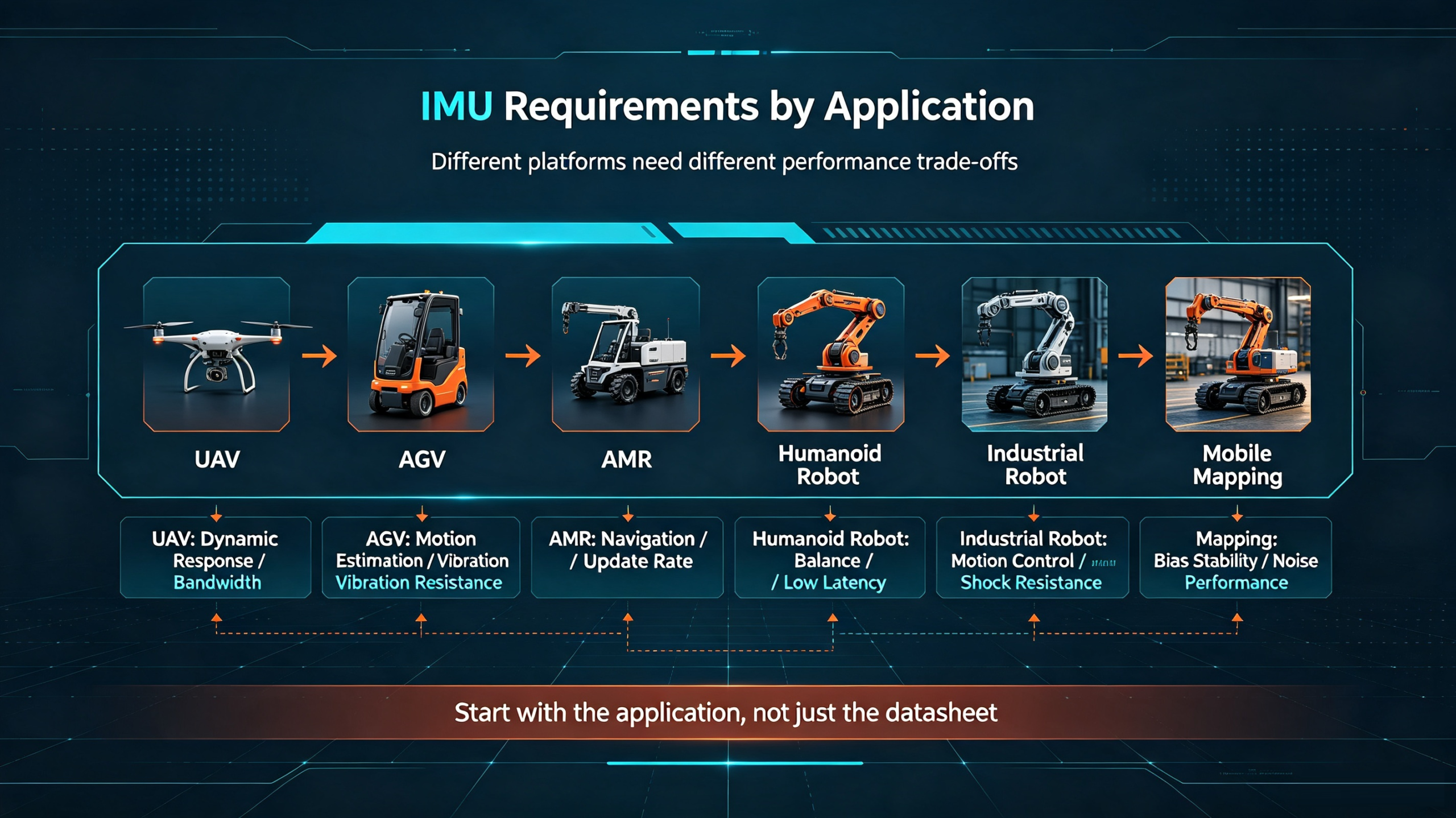
IMU Requirements by Application
Different applications require different combinations of performance.
| Application | Main Requirement | Important IMU Parameters |
|---|---|---|
| UAV | Dynamic response | Gyro range, bandwidth, update rate |
| AGV | Stable motion estimation | Bias, noise, vibration resistance |
| AMR | Navigation and motion sensing | Bias, ARW, VRW, update rate |
| Humanoid Robot | Dynamic Balance | Low latency, gyro performance |
| Industrial Robot | Motion Control | Range, bandwidth, vibration |
| Mobile Mapping | Measurement accuracy | Bias stability, noise, temperature |
| Marine System | Long-term Stability | Gyro bias, accelerometer bias |
| Mining Equipment | Harsh Environment | Temperature, shock, vibration |
| Autonomous Vehicle | Navigation | Bias, noise, range, stability |
This table illustrates why there is no universally "best IMU."
An IMU designed for a small UAV does not necessarily represent the best solution for a surveying platform.
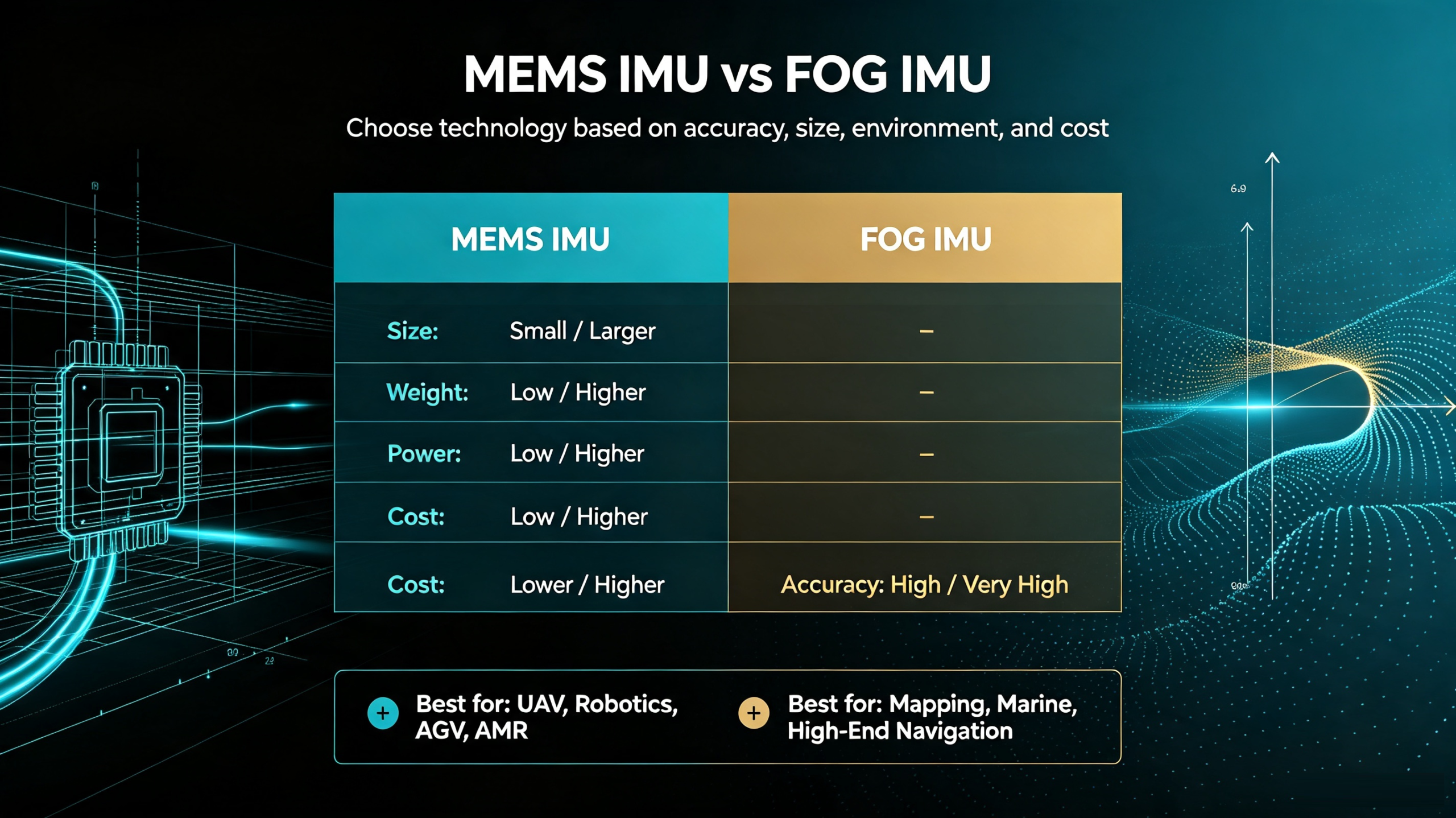
MEMS IMU vs FOG IMU
One of the most important decisions in inertial sensor selection is choosing between MEMS and FOG technology.
MEMS IMU
MEMS IMUs use microelectromechanical sensors.
Their major advantages include:
- Compact size
- Low weight
- Low power consumption
- Lower cost
- Easy integration
- High scalability
This makes MEMS IMUs attractive for:
- UAVs
- Robotics
- AGVs
- AMRs
- Autonomous systems
- Industrial automation
FOG IMU
Fiber-optic gyroscope-based systems generally provide higher inertial performance for demanding navigation applications.
Their advantages can include:
- Lower drift
- High stability
- Excellent long-term performance
- High navigation accuracy
However, they can involve:
- Higher cost
- Larger size
- Higher power consumption
- More complex integration
A simplified comparison is:
| Parameter | MEMS IMU | FOG IMU |
|---|---|---|
| Size | Small | Larger |
| Weight | Low | Higher |
| Power | Low | Higher |
| Cost | Lower | Higher |
| Accuracy | High | Very High |
| UAV | Excellent | Application dependent |
| Robotics | Excellent | Application dependent |
| Mapping | Application dependent | Excellent |
| High-end navigation | Application dependent | Excellent |
The correct technology depends on the application's accuracy, size, budget, and environmental requirements.
How to Match IMU Performance to Your Project
Instead of starting with a product model, engineers should begin with application requirements.
A practical selection process can follow these steps:
Step 1: Define the Motion
Determine:
- Maximum angular velocity
- Maximum acceleration
- Typical operating dynamics
Step 2: Define the Accuracy
Determine whether the system needs:
- Basic motion measurement
- Stable attitude estimation
- Precision mapping
- High-accuracy navigation
Step 3: Define the Environment
Consider:
- Temperature
- Vibration
- Shock
- Humidity
- Electromagnetic environment
Step 4: Define the Integration Constraints
Check:
- Size
- Weight
- Power
- Interface
- Mounting
- Data protocol
Step 5: Select the Technology
Choose between:
MEMS → high integration and cost efficiency
or
FOG → higher inertial performance for demanding applications
This process is more reliable than selecting a sensor solely from a product catalog.
IMU Selection Checklist: 10 Questions to Ask Before Buying
Before purchasing an IMU, engineers should confirm the following:
1. What gyroscope bias instability does the application require?
2. What accelerometer bias is acceptable?
3. What ARW and VRW performance is required?
4. What maximum angular velocity will the platform experience?
5. What maximum acceleration will occur?
6. What update rate and bandwidth does the control system need?
7. What temperature range will the IMU operate in?
8. What vibration and shock levels must it withstand?
9. What interface and communication protocol are required?
10. Does the supplier provide calibration, documentation, customization, and technical support?
A supplier that can provide clear answers to these questions is generally better positioned to support an industrial integration project.
ERICCO MEMS IMU Solutions
ERICCO develops MEMS and FOG-based inertial products for applications including aerospace, marine navigation, oil and gas, mining, UAVs, robotics, and industrial systems.
Its MEMS IMU portfolio provides different performance levels for different application requirements.
For example, the ER-MIMU-M02 is designed as a compact MEMS inertial measurement solution for applications requiring integrated inertial sensing with low size and weight.
For higher-accuracy applications, Ericco also provides mapping-level MEMS inertial navigation solutions designed for applications where sensor performance directly affects positioning and measurement results.
When selecting an Ericco IMU, engineers should compare the actual specifications of each model—including:
- Gyroscope bias
- Accelerometer bias
- Gyroscope range
- Accelerometer range
- ARW
- VRW
- Update rate
- Operating temperature
- Communication interface
- Size and weight
This allows the sensor to be matched to the application rather than selected purely by product category.
Note: Product specifications should always be checked against the latest Ericco datasheet before final procurement because configuration and specification options may vary by model.
Common IMU Selection Mistakes
Mistake 1: Choosing Only by "Accuracy"
"Accuracy" is not one single parameter.
Engineers should separately evaluate:
- Bias
- Noise
- ARW
- VRW
- Scale factor
- Temperature performance
- Dynamic performance
Mistake 2: Ignoring Accelerometer Performance
A good gyroscope does not automatically make a good navigation IMU.
Accelerometer bias and noise can become major error sources in navigation applications.
Mistake 3: Confusing ARW with Bias Stability
These parameters describe different aspects of sensor performance.
ARW relates primarily to angular measurement noise, while bias instability describes longer-term bias behavior.
Both should be considered.
Mistake 4: Choosing the Maximum Measurement Range
More range is not always better.
The range should match the actual dynamics of the application while preserving sufficient measurement resolution.
Mistake 5: Ignoring Temperature
Industrial equipment rarely operates at a constant room temperature.
Temperature performance should be evaluated before final sensor selection.
Mistake 6: Ignoring Vibration
A sensor mounted on a stable laboratory platform may perform differently when installed next to a motor, gearbox, propeller, or heavy mechanical actuator.
Always evaluate the actual installation environment.
FAQ
Q: What is the most important specification when choosing an IMU?
A: There is no single specification that is most important for every application. Gyroscope bias, accelerometer bias, ARW, VRW, range, bandwidth, temperature performance, and vibration resistance should be considered together.
Q: What is a good gyroscope bias for an industrial IMU?
A: The required value depends on the application. Basic motion sensing can tolerate higher bias, while precision navigation and mapping require significantly better long-term stability.
Q: Is 200 Hz enough for an IMU?
A: For many industrial and robotic applications, 200 Hz can be sufficient. However, highly dynamic control systems may require higher bandwidth and faster response.
Q: What is ARW in an IMU?
A: Angle Random Walk is a measure related to gyroscope noise and helps describe short-term angular measurement performance.
Q: What is VRW in an IMU?
A: Velocity Random Walk characterizes the contribution of accelerometer noise to velocity uncertainty.
Q: Should I choose a MEMS or FOG IMU?
A: MEMS is usually attractive when size, weight, power consumption, cost, and integration are important. FOG becomes more attractive when extremely low drift and high navigation performance are required.
Q: Can an IMU work without GNSS?
A: Yes. An IMU can measure angular velocity and acceleration independently of GNSS. However, inertial errors accumulate over time, so many navigation systems combine IMU data with GNSS or other external references.
Q: What interface should an industrial IMU use?
A: The answer depends on the host controller. Common interfaces include UART, RS232, RS422, CAN, and SPI. Compatibility should be confirmed before procurement.
Q: How should an IMU be mounted?
A: The IMU should be firmly mounted and aligned with the system coordinate frame. Loose mounting, incorrect axis orientation, and excessive vibration can introduce significant errors.
Conclusion: Choosing the Right IMU
Selecting an IMU is ultimately an engineering optimization problem.
The correct choice depends on the relationship between:
Accuracy + Stability + Dynamics + Environment + Integration + Cost
A UAV may prioritize low weight, low power consumption, high update rate, and sufficient gyroscope range.
An industrial robot may prioritize low noise, bandwidth, vibration resistance, and compact integration.
A mapping system may require much lower sensor bias and better long-term stability.
A mining vehicle may prioritize temperature, shock, and vibration performance.
Therefore, the best IMU is not necessarily the most expensive or the highest-performance product.
It is the IMU that provides the right level of performance for the actual application.
For many modern autonomous and industrial systems, MEMS technology provides an effective balance between performance, size, weight, power consumption, and cost. When the application demands significantly higher inertial stability, FOG-based technology may provide a better solution.
Before making a final purchasing decision, engineers should compare the complete sensor specification, environmental performance, interface, integration requirements, calibration capabilities, and supplier support.
If you are selecting an IMU for UAVs, robotics, autonomous vehicles, mapping, marine navigation, mining, or industrial automation, define your system requirements first and then select the IMU that meets those requirements.