

1. Overview of the overview
This document describes how the product works, its main performance indicators and its use.
The main content provided by this document is:
Introduction of ER-POS1A Land Positioning and Orientating System;
The working principle of ER-POS1A Land Positioning and Orientating System;
Brief introduction of ER-POS1A Land Positioning and Orientating System;
Introduction of the System Software for ER-POS1A;
Use of the directional positioning system for ER-POS1A;
2. Term
| FOG | Fibre OpticGyroscope |
| IMU | Inertial Measurement Unit |
| INS | Inertial Navigation System |
| SINS | Strapdown Inertial Navigation System |
| GPS | Global Positioning System |
3. Introduction of Land directional Positioning system
3.1 working principle
The ER-POS1A Land Positioning and Orientating System adopts a three-axis optical fiber gyroscope sensitive carrier angular motion to output a digital signal which is proportional to the motion angular rate of the carrier, the current signal is converted into a frequency signal through the I/ F conversion circuit into a frequency signal to be input into the navigation computer. The navigation computer completes the data reception of the gyroscope, the accelerometer, the external GPS, the system error compensation calculation, the navigation and the calculation, and transmits the real-time speed, position, attitude and other navigation information to the outside through the monitoring port at a predetermined period.

Fig.1 ER-POS1A Land Positioning and Orientating System
3.2 Form
ER-POS1A Land Positioning and Orientating System
(1): built-in three-axis fiber-optic gyroscope, three quartz flexible accelerometers and uniaxial rotation mechanism. The navigation computer completes the data reception of gyroscope, accelerometer, external GPS, system error compensation calculation, navigation calculation, and transmits real-time navigation information such as speed, position and attitude through the monitoring port through the specified period.
Satellite antenn
(2): the product is equipped with 2 GNSS (BD optional) positioning antenna;
Feeder
(2): both ends of the antenna feeder are TNC male head, standard 5 meters, one end connected to satellite antenna, one end connected to the main product;
Data / power cable (3): 1 data cable, supporting one RS-232 interface, two RS-232 / RS-422 (configurable) interfaces, one USB interface, one CAN interface, four odometer interfaces, one PPS interface; Power cable, support 24VDC rated power supply, suitable for 10~32VDC wide voltage range; a network cable.
PC software: through the PC software, the protocol data returned by the device can be analyzed, and the navigation data can be displayed in real time and stored accordingly.
3.3 Function and scope of use
The main functions of ER-POS1A series Land Positioning and Orientating System include:
1) angular rate and acceleration measurement;
2) self-searching function;
3) the attitude tracking function;
4) combining the navigation function;
5) RS-422/RS232 serial communication.
ER-POS1A Land Positioning and Orientating System can complete the data reception of gyroscope, accelerometer, external GPS, system error compensation calculation, navigation calculation, and transmit real time speed and position through the monitoring port through the specified period. Attitude and other navigation information. At the same time, it is a dynamic working mode with high precision and good reliability. It provides the information of motion, speed and position of the vehicle. For missile launch, weapon aiming, radar, antenna, vehicle and other dynamic initial alignment, static initial alignment, direction control and other objects.
3.4 Main performance parameters
pure navigation mode
The initial alignment of ER-POS1A is divided into two ways of unit setting static alignment and double-position alignment. The positioning accuracy of double-position alignment is higher than that of unit set static alignment.
l Azimuth alignment accuracy: 0. 01 ° sec (Φ), (1 σwith local latitude);
l The accuracy of horizontal attitude alignment is ≤ 0.02 °(1 σ);
l Azimuth accuracy: 0.05 °/ h;
l Horizontal attitude holding accuracy: 0.03 °/ h;
l Positioning accuracy (50% CEP): 1992nm/ h (10min static alignment);
l Horizontal velocity accuracy (RMS): ≤ 2m/s (10min static alignment);
l Positioning accuracy (50% CEP): 1nm/ h (double-position alignment, alignment time less than 30min);
l Horizontal velocity accuracy (RMS): ≤ 1m/s (double position alignment, alignment time less than 30min);
GPS auxiliary navigation mode
l Azimuth alignment accuracy: {0. 01 ° sec (1σ,Φ with local latitude);
l The accuracy of horizontal attitude alignment is ≤ 0.02 °(1 σ);
l Azimuth retention accuracy: ≤ 0. 05 °sec (Φ) (1 σ, Φ is local latitude);
l The accuracy of horizontal attitude holding is ≤ 0.01 °(1 σ);
l Positioning accuracy: ≤ 5m (1 σ);
l Velocity accuracy: ≤ 0.1m/s (1 σ).
4. Programme brief
The internal inertial measurement unit (INERTIAL MEASUREMENT UINT-IMU) of the ER-POS1A land orientation positioning system consists of a three-axis fiber optic gyroscope, three quartz flexible accelerometers and a uniaxial rotation mechanism.
4.1 Fibre Optic Gyroscope
Fiber optic gyroscope (FOG) is an optical fiber interferometer based on the (Sagnac) effect of Sagger Naik, which is composed of two beams of interference propagating in the same optical fiber sensing ring, which forms an optical fiber Sagnac interferometer, as shown in figure 2.

Fig. 2 schematic diagram of fiber optic gyroscope
The beam splitter / beam combiner from the light source is divided into two beams, which are coupled into the fiber sensing coil from both ends of the optical fiber loop and propagate clockwise and counterclockwise. Two beams of light from both ends of an optical fiber loop are superimposed by a splitter / beam combiner to produce interference. the resulting phase difference is proportional ![]() to the rotational angular velocity of the ring:
to the rotational angular velocity of the ring:
![]() …………………………………………(1)
…………………………………………(1)
Of which,
L fiber length;
D Average diameter of Fiber Ring;
The wavelength of light in a vacuum;
The Velocity of Light in vacuum
Angular velocity information can be obtained by detecting the phase difference (i.e., interference light intensity), where the term is the scale factor of the gyro.

Fig. 3 Real object diagram of the optical fiber ring
The optical fiber gyroscope adopts a high-precision three-axis optical fiber gyroscope, and the optical fiber gyroscope adopts a full-digital closed-loop optical fiber gyroscope solution, and the optical path part is composed of a light source, a coupler, an integrated Y-wave guide, an optical fiber sensing ring and a detector. In the scheme of the common doped fiber-doped fiber light source, the three optical fiber sensing ring turns are respectively sensitive to angular movement in three directions, and the processing of the signals and the output angle rate information are completed by the corresponding circuit board.

Fig 4 Block diagram of the light source scheme
In the process of development, several key technologies, such as erbium-doped fiber source technology, zero-start technology and scaling factor error control technology, are broken through, which makes the fiber optic gyroscope operate in the temperature range of -10 ℃~50 ℃, under the condition of zero start. The zero bias stability is better than 0.02 / h (1 σ).
The main technical indexes are as follows:
Preparation time: 15s;
Zero bias stability (mean time 100s)≤0.02/h(1σ);
Zero bias repeatability (stable environment, average time 100s)≤0.02(1σ) /h;
Random walk coefficient ≤ 0.005 ;
Scale factor nonlinearity ≤ 50 ppm;
Scale factor repeatability ≤ 50 (1 σ) ppm;
Gyro measurement range is not less than ±300 / s.
| Apply | Measurement labor | drift mobility(%) | accuracy class |
| Tactical missile, carrier rocket, launch boat | According to the need, | >10 | Low precision (general control) |
| Medium and short range missile, general aircraft, satellite | >100(o)/s | 1~10 | Medium accuracy (tactical level) |
| Medium range missile, general aircraft, satellite | >100(o)/s | 0.1~1.0 | Medium accuracy (tactical level) |
| Long-range missiles, military aircraft, submarines, satellites | >100(o)/s | 0.01~0.1 | Medium precision (tactical level) |
| Strategic Missile, Space Shuttle, Submarine, Satellite | >10(o)/s | 0.001 | High precision (inertial navigation stage) |
4.2 Accelerometer
The accelerometer adopts quartz flexible accelerometer. Quartz flexible accelerometer is a mechanical pendulum force balance accelerometer, which consists of two parts: the head and the servo circuit. The head is composed of integral quartz flexible inspection quality pendulum assembly, upper and lower torque device, belly belt and isolation ring, shell and other parts. The servo circuit is a hybrid integrated circuit, which consists of a reference triangular wave generator, a differential capacitance detector, a current integrator, a transconductance compensation amplifier and a voltage regulator.
The accelerometer is mounted on the carrier. When the carrier has acceleration motion relative to the inertial space in the input axis of the accelerometer, the mass pendulum of the accelerometer will produce inertia torque, and:
Mg =mLai …………………………………………(2)
Of which,
Mg-measuring the inertia moment of a mass pendulum;
M-check the quality of the pendulum;
L-measuring the distance between the mass center of a mass pendulum and a flexible pivot;
Ai-accelerometers input acceleration along the axis.
The inertia moment causes the measuring quality pendulum to produce the angular displacement around the flexible pivot. The angular displacement causes the differential capacitance sensor to produce the capacitance difference value, when the small angle displacement:
Δc =KpΔα…………………………………………(3)
Of which,
Δ c-capacitance difference;
Kp-the transfer coefficient of a differential capacitance sensor near zero;
Δ a-the angular displacement of a mass pendulum.
The capacitance difference is converted into a current signal by the servo circuit, and the current output torque generator generates an electromagnetic feedback moment.
Mt =Kt I …………………………………………(4)
Of which,
The feedback moment of the Mt/ F moment device;
The moment coefficient of the Kt brushless torque device;
I-the current that goes through the torquer coil.
When Mt = Mg:
I=(mL/Kt )ai…………………………………………(5)
Of which,
ML/Kt-the current scaling factor, the feedback current required when the input acceleration is 1 g.
When the feedback torque of the torquer is balanced with the inertia moment of the detected mass pendulum, the current required in the torquer coil is proportional to the input acceleration. Therefore, the acceleration of the carrier along the input axis of the accelerometer can be measured by measuring the current value flowing through the torquer coil when the torque is balanced.
The main technical indexes are as follows:
Measuring range: -20g~+20g;
Threshold value: not more than 5×10⁻⁶g;
Scale factor monthly repeatability: not more than 3.5×10⁻⁵ (1σ);
Scale factor temperature coefficient: not more than 6×10⁻⁵/℃(-40°C~+60°C);
Second order nonlinear coefficient: not more than 3×10⁻⁵g/g2;
Deviation value: not more than 6×10⁻³g;
Deviation temperature coefficient: not more than 2.5×10⁻⁵g/℃(-40°C~+60°C);
Monthly repeatability: not more than 2.5×10⁻⁵g (1s);
Bandwidth: not less than 800Hz.
5. performance index
ER-POS1A Land Positioning And Orientating System includes many navigation modes and can be integrated with GPS.
5.1 Pure navigation mode
The initial alignment of ER-POS1A can be divided into two ways: single position static alignment and double position alignment. The positioning accuracy of dual position alignment is higher than that of single position static alignment.
Azimuth alignment accuracy: ≤0.01°sec (Φ) (1σ, Φis local latitude);
The accuracy of horizontal attitude alignment is: ≤0.02° (1σ);
Azimuth accuracy: 0.05°/h;
The accuracy of horizontal attitude holding is: 0.03°/h。
Positioning accuracy (50% CEP): ≤2nm/h(10min static alignment);
Horizontal velocity accuracy (RMS): ≤2m/s(10min static alignment);
Positioning accuracy (50% CEP): ≤1nm/h(double-position alignment, alignment time less than30min);
Horizontal velocity accuracy (RMS): ≤1m/s(double-position alignment, alignment time less than30min).
5.2 GPS auxiliary navigation mode
Azimuth alignment accuracy:≤0.01°sec (Φ)(1σ, Φis local latitude);
The accuracy of horizontal attitude alignment is: ≤0.02°(1σ);
Azimuth holding accuracy: ≤0.05°sec(Φ)(1σ, Φis local latitude);
The accuracy of horizontal attitude holding is: ≤0.01° (1σ).
Positioning accuracy: ≤5m (1σ);
Velocity accuracy: ≤0.1m/s(1σ).
5.3 Other
Shape size: 248×248×180[It can be customized to customer requirement];
weight: ≧20kg;
Data measurement frequency: 20Hz~2000Hz;
Power supply: AC220V 50 Hz / AC110V 60 Hz / DC18V ~ 36 v;
Power consumption: less than 50W;
Operating temperature: -40℃~+60℃;
storage temperature: -45℃~+80℃。
6. Initial alignment
The alignment process of ER-POS1A Land Positioning and Orientating System is divided into two stages: coarse alignment and fine alignment.
6.1 Coarse alignment
The first 130 s after the inertial navigation system is powered up is the coarse alignment stage. In order to obtain better alignment effect, we should try our best to ensure that no acceleration motion is carried out at this stage, but not to limit the swing motion (such as the idle state of the vehicle).
6.2 Fine alignment
After 180s, the inertial navigation system automatically turns to the precision alignment stage.
The dual position alignment algorithm is used in the precision alignment, that is to say, the course of the product should be changed twice during the alignment process. Under the condition that the alignment reference information (GPS/DVL) is effective, the carrier can move without restriction, but in order to achieve higher alignment accuracy, the following alignment routes are recommended: one course maneuver (change above 70 °) at the inertial navigation system (10min) and a second maneuver around the 20min (the carrier course recovers to the forward target direction). The maneuvering process is shown in figure II-1.

Fig 5 Recommended alignment route schematic
If the reference information is invalid, you can change course in situ for fine alignment.
The alignment time is 1400m 1600s. If the reference information is invalid, the alignment time is prolonged accordingly.
7. Interface definition
7.1 Coordinate system definition
Carrier coordinate system (b system)──: The Origin of Carrier coordinate system O is selected in the Inertial Navigation Center,Xb axis is the front of the longitudinal axis, Yb axis is horizontal and refers to the right, form the right hand coordinate system. The installation of gyroscopes and accelerometers is in accordance with the carrier coordinate syste munanimous.
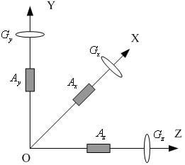
Fig 6 Coordinate system definition diagram
The geographical coordinate system (t system)──The origin of the geographical coordinate system O is selected at the center of gravity of the carrier,Pointing north,Pointing to the sky in a vertical direction, Point east.
The navigational coordinate system (n system)──The navigation coordinate system coincides with the geographical coordinate system.
When the ER-POS1A Land Positioning and Orientating System is installed on the carrier, the X axis should be consistent with the longitudinal axis of the carrier.
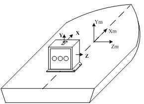
Fig 7 Installation of ER-POS1A on carrier
The ER-POS1A attitude angles are defined as shown in figure II-5:
| Path angle Counterclockwise is positive, clockwise is negative-180º~+180º | 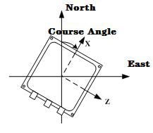 |
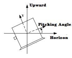
| Angle of pitch
Head up for positive, bow for negative-90º~90º |
 |
| Roll position
The right tilts to the positive and the left to the negative-180º~180º |
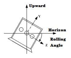 |
Fig. 8 attitude angle definition