

1. Overview
Mine north finder is based on three-axis integrated fiber optic gyro and three-axis accelerometer, which can complete the initial alignment, attitude maintenance function, real-time output carrier attitude reference value.
The invention is a method for measuring the attitude of a downhole drilling machine. It is fixed on the track of the rig propeller. After starting work, the angular velocity of the sensitive rotational motion and the acceleration of the translational motion are solved in the posture of the processor to obtain the attitude of the rig. Then, the inertial measurement system continuously measures the current rig's current position. Attitude until the end of the measurement. The invention can automatically and quickly and accurately measure and display the posture information of the downhole drilling rig without relying on the external information by means of the external information.
This North Finder is specially developed for coal mines. It reduces the cost of using the North Finder and has stable performance. Many companies have a strong interest in it and express their intention to cooperate with us.
2. Product Features and Technical Indicators
2.1 Common Requirements
Start time(from powered on to the data output) <5seconds
Find the north time(from the system starting to the precise output)≤5min
System weight ≤1.6kg
System measurement 200mm×100mm×90mm
Communication Interface: RS422 serial port
Data refresh rate: 1000HZ
Working temperature: 5℃~55℃;
Storage temperature: -40℃~+60℃
2.2 North Finding Accuracy
Find north way Stationary base
Find the north time: 5min
Azimuth measurement range: 0°~360°
Inclination measurement range: -30°~+30°
Inclination measurement accuracy: ≤0.2°
Azimuth measurement accuracy ≤2.0°
Azimuth retention time: 10min
Voltage direct current: 12V±1v
Power static: 12.0V operating voltage<15W
dynamic: 12.0V operating voltage ≤20W
Product life cycle: MTBF>5000h
Meet the requirements of vibration impact environment and electromagnetic compatibility of shearer.
Vibration max5.0g frequency range 10Hz ~1000Hz sweep rate≤ 1 oct/min
Shock :accelerate 20.0g pulse time of duration (11±1) ms half-sine wave
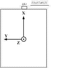
The coordinate axis of the DBY series north seeker are defined in Figure 1. The X axis is along the direction of the system connector. When the system is installed on the bottom four mounting flanges, the Z axis defines the skyward direction. X, Y, Z constitute the Cartesian orthogonal coordinate system.
The system output heading angle/azimuth angle indicates: the positive direction of Y axis and the angle of geographic north, and the direction of increasing the angle of north east.
The system output pitch angle/tilt angle indicates: the positive angle between the Y axis and the horizontal plane, positive on the upper side.
3. Device Interface Definition
3.1 Data Interface Definition
The SX1 connector leads to a DB9 female connector, which is connected to a standard four-wire RS422. Users only need to connect the above serial port to the acquisition computer for measurement. Note that the baud rate is 614.4 kbps, which requires a matching acquisition device for data acquisition.
3.2 Hardware Interface Definition
DBY series north finder adopts RS422 serial port output. The baud rate is 614.4Kbps. Each frame has a total of 60 bytes. Each byte contains 1 start bit (0), 8 data bits, 1 stop bit (1), each word. The lower part is transmitted first in the section, and the low byte is transmitted first for each frame of data, and there is no verification at this moment. The specific data format is shown in the following table:
Table 1 data frame format
| Bytes (60 bytes in total) | Data content | Supplementary explanation |
| 1~4 | Frame header | 0X EB8055AA |
| 5~8 | X Gyro Data | Low first and then high,Dimensionless digital quantity |
| 9~12 | Y Gyro Data | Low first and then high,Dimensionless digital quantity |
| 13~16 | Z Gyro Data | Low first and then high,Dimensionless digital quantity |
| 17~20 | X Accelerometer data | Low first and then high,Dimensionless digital quantity |
| 21~24 | Y Accelerometer data | Low first and then high,Dimensionless digital quantity |
| 25~28 | Z Accelerometer data | Low first and then high,Dimensionless digital quantity |
| 29~32 | latitude | Low first and then high,0.000001° |
| 33~36 | longitude | Low first and then high,0.000001° |
| 37~40 | height | Low first and then high,1m |
| 41~44 | counter | Low first and then high,2.5ms |
| 45~46 | Pitch angle/tilt angle | Low first and then high,0.01° |
| 47~48 | Roll angle | Low first and then high,0.01° |
| 49~50 | Heading/azimuth | Low first and then high,0.01° |
| 51~56 | Pending byte | |
| 57~60 | End of frame | 0X FF000034 |
4. Related Acquisition Software Instructions
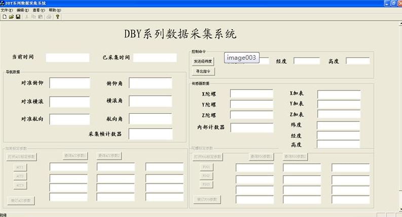
DBY series north finder acquisition software as shown below:
Navigation data module: After the system seeks north, the alignment information is displayed on the left side of the area, and the right part tracks the system's three-dimensional posture information in real time.
Control command module: "North seeking instruction" can be re-searched in the case of uninterrupted power; latitude, longitude, height of the three edit boxes can be entered in the current work location latitude and longitude (mobile phone positioning is ok ), after the input is complete, click "latitude and longitude "longitude and latitude information can be stapled and instantly written into the system's internal memory. After sending is complete, click "Search North" to search for north under the new input latitude and longitude, and the power is not lost. On the upper computer interface, "upper machine" - "latitude" The latitude, longitude, and altitude data are updated to the new latitude and longitude to indicate successful stapling.
Sensor data module: includes gyro and accelerometer raw output data; the internal counter counts for power on, clicks“seeking north command”and clears it; latitude, longitude, and height are bound information.
The data is stored in the current directory of the software and named as“0924205117imu_data.txt” (document creation time). The data columns are three-axis gyros, three-axis plus tables, three-axis attitude angles, latitude, longitude, and altitude.
5. Test process and data
DBY series north finders need to be tested in the correct operating order. The test procedure is briefly described as follows:
(1) System installation: The DBY series north finder is fixed on the test bench reference plane through the bottom;
(2) Connector connection: Connect the power supply and data interface as required. Refer to Section 3 for details.
(3) Power ups: After the external linear power supply is determined to be debugged, check the connection between the parts, and then turn on the external linear power supply, and check whether the power supply current is within the normal power consumption range. If the current is too large or too large in small cases, it is necessary to check for power failure and the test can be continued under the correct current size.
(4) System work: After the system is powered on, the data interface connected to the SX1 should have data output. Refer to Part 3 for the format. You can use the provided DBY series north finder acquisition software to collect data. After the system is powered on, you need to 3 minutes alignment time (seeking north time), as far as possible within 3 minutes to ensure that the system is in a static state, after the completion of the alignment (after 3 minutes) to enter the navigation phase, then turn the bearing device, north finder can track three in real time change the attitude angles. If you need to re-align (find the north), click on the third part and click the “North Seeking Instructions” button to perform north seeking again.