

Introduction
In autonomous unmanned aerial vehicle (UAV) navigation, positional accuracy alone is insufficient. Whether an industrial drone is conducting high-precision LiDAR mapping, inspecting high-voltage power lines in severe electromagnetic environments, or executing complex Beyond Visual Line of Sight (BVLOS) maneuvers, positional data is only as good as the aircraft's spatial awareness.
This is where the Attitude and Heading Reference System (AHRS) serves as the central neural hub of the UAV flight control system.
While basic Inertial Measurement Units (IMUs) provide raw angular rate and acceleration data, a high-performance UAV Attitude Sensor continuously computes roll, pitch, and true heading by fusing raw sensor data with advanced estimation algorithms (such as the Extended Kalman Filter).
This guide delivers an end-to-end technical breakdown of drone attitude sensing from mathematical foundations and sensor noise modeling to real-world integration challenges, multi-sensor calibration, and commercial selection.
Core Principles: How an AHRS Works
To understand the operational mechanics of an AHRS for UAV platforms, it is critical to distinguish between an IMU, an AHRS, and a full Inertial Navigation System (INS).
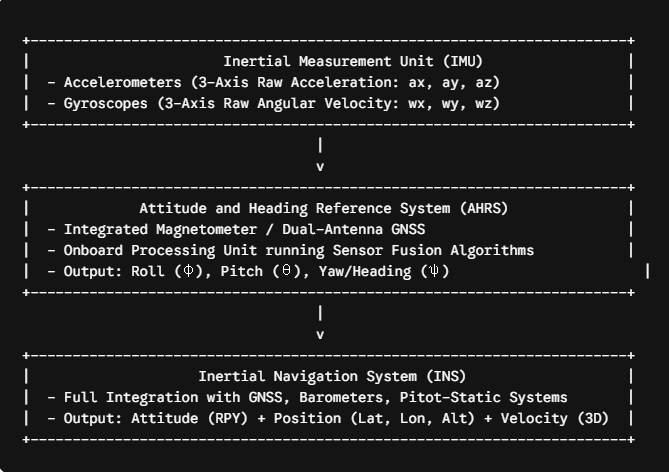
Sensor Triad and Kinematic Equations
An AHRS consists of a 9-axis sensor triad:
-
3-axis MEMS Gyroscope: Measures angular velocity (ω_x, ω_y, ω_z).
-
3-axis MEMS Accelerometer: Measures specific force/linear acceleration (a_x, a_y, a_z).
-
3-axis Magnetometer: Measures local geomagnetic field vectors (m_x, m_y, m_z).
To determine aircraft orientation, the angular rates from the gyroscope are integrated over time. The dynamic relation between Euler angle rates and body-frame angular velocities (p, q, r) is expressed as:
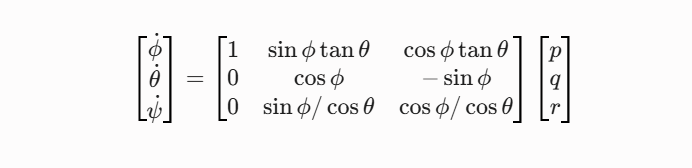
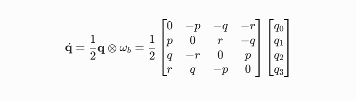
Because direct Euler integration suffers from mathematical singularities (specifically Gimbal Lock at pitch angles θ = ±90°), modern industrial flight controllers represent attitude using unit quaternions:

The quaternion derivative equation used for real-time integration is:
The Cumulative Drift Problem
If gyroscopes were perfectly stable, numerical integration of q would yield exact attitude over time. However, real-world MEMS gyroscopes exhibit zero-bias instability, thermal drift, and random walk noise.
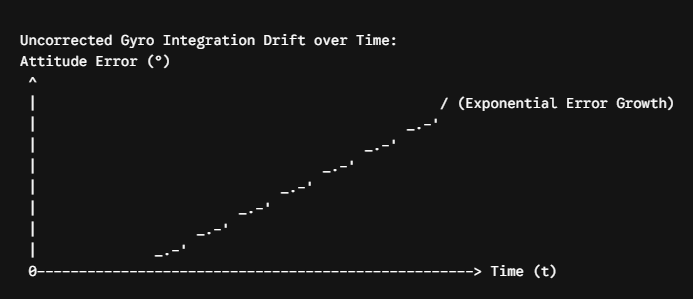
Integrating uncalibrated gyroscope bias causes the calculated orientation to drift indefinitely. To bound this error:
-
Accelerometers reference Earth's gravity vector (g ≈ 0.98m/s² ) to constrain Roll and Pitch drift.
-
Magnetometers (or dual-antenna GNSS arrays) reference Earth's magnetic north field to constrain Yaw/Heading drift.
Sensor Fusion Algorithms: EKF vs. Complementary/Mahony Filters
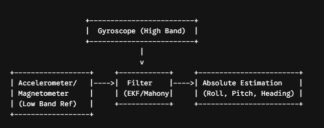
Fusing high-rate dynamic gyroscopic data with low-rate, absolute references (accelerometer and magnetometer) requires mathematical filtering. The two dominant paradigms in commercial and tactical UAVs are:
-
Extended Kalman Filter (EKF):
-
Mechanism: Linearizes nonlinear flight kinematics around the current state estimate. It continuously models noise covariances (Q and R) to dynamically weight sensor reliability.
-
Strengths: Handles linear acceleration and transient magnetic interference; updates sensor bias real-time (b_g, b_a).
-
Applications: Fixed-wing BVLOS, industrial VTOLs, defense-grade navigation.
-
-
Complementary & Mahony Explicit Complementary Filters (ECF):
-
Mechanism: Employs high-pass filtering on gyroscopes and low-pass filtering on accelerometers/magnetometers, using a proportional-integral (PI) feedback loop to drive estimation error toward zero.
-
Strengths: Extremely low computational overhead, zero matrix inversion requirement, rapid execution on lower-power MCUs (ARM Cortex-M4/M7).
-
Applications: Lightweight micro-UAVs, high-speed racing drones, budget-constrained flight controllers.
-
Key Error Sources and Mitigation in UAV Environments
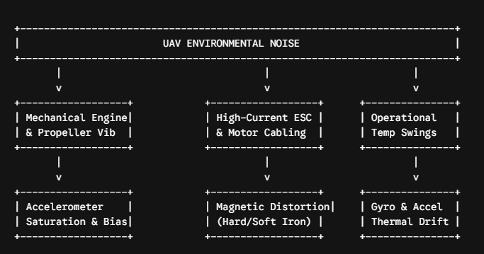
Deploying an Industrial AHRS onboard a multirotor or fixed-wing aircraft presents severe noise and environmental challenges. Understanding these physics-based error mechanisms is critical for reliable systemic design.
1. Vibration and Accelerometer Saturation
High-frequency mechanical vibrations from brushless DC motors and unbalance in carbon fiber propellers propagate into the airframe within the 100 Hz–1000 Hz spectrum.
-
Mechanism: High-amplitude vibration causes MEMS accelerometer proof-mass structures to hit internal physical stops (rectification error), shifting the mean DC acceleration output.
-
Consequence: The EKF misinterprets structural vibration as continuous linear acceleration, skewing pitch and roll estimation by up to 15°–20°.
2. High-Dynamic Maneuvers & Non-Gravitational Acceleration
The accelerometer-based roll/pitch correction assumes the only measured continuous acceleration vector is Earth's gravity (g).
-
Mechanism: During centripetal turns, rapid acceleration, or sudden braking, the measured acceleration is a_meas = g + a_kinematic.
-
Consequence: Simple complementary filters treat centrifugal acceleration as gravity, artificially leaning the calculated horizon away from true level. Modern industrial AHRS engines bypass this issue using kinematic motion models or external velocity feedback from GNSS/airspeed sensors to subtract a_kinematic before the measurement update phase.
3. Magnetic Distortions (Hard Iron vs. Soft Iron)
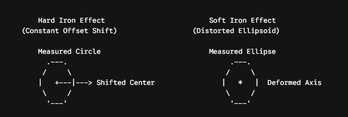
Magnetometers are sensitive to distortion from local structural and electrical materials:

-
Hard Iron Interference: Caused by permanently magnetized components onboard (e.g., steel fasteners, battery nickel strips, motor magnets). It creates a constant vector bias (V_hard_iron) that shifts the center of the magnetic field sphere away from the coordinate origin.
-
Soft Iron Interference: Caused by magnetically permeable materials (e.g., structural iron, structural carbon fiber weaves, adjacent power buses) that alter and deform the shape of Earth's magnetic field into an ellipsoid (A_soft_iron).
-
Dynamic EMI: High-current power distribution boards (PDBs) and ESC supply wires generate time-varying magnetic fields (I ∝ B) proportional to throttle percentage, rendering static magnetometer offsets useless during climb or acceleration.
4. Thermal Drift
MEMS silicon structures deform slightly over temperature gradients (-40°C to +85°C), inducing thermal shifts in bias offset, scale factor, and axis alignment. Without hardware-level, active thermal compensation, cold-weather takeoffs or internal heat generation from onboard compute modules can lead to severe attitude degradation during flight.
3. Engineering Hardware Integration & Calibration Guide
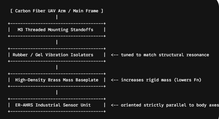
To achieve stable, tactical-grade flight performance from an AHRS for UAV integration, hardware engineers must follow strict mounting, mechanical isolation, and calibration protocols.
Physical Mounting and Vibration Isolation
-
Center of Gravity (CoG) Placement: Position the AHRS as close as possible to the aircraft’s physical CoG. Off-center mounting induces lever-arm acceleration forces (a_lever = α*r+ω) during rapid yawing or pitching, requiring manual lever-arm vector compensation in software.
-
Resonant Frequency Decoupling: Mount the AHRS on a tuned dampening mass plate (typically a weighted PCB or brass plate suspended by silicone/rubber dampening grommets). Ensure the natural mechanical frequency of the isolator ($f_n$) satisfies: