

Quick Answer: What Causes IMU Errors?
Common IMU errors are mainly caused by gyroscope bias, accelerometer bias, sensor noise, scale-factor errors, axis misalignment, temperature changes, vibration, shock, installation problems, and calibration errors.
These errors can produce symptoms such as attitude drift, noisy measurements, inaccurate velocity, position drift, or inconsistent performance under different environmental conditions.
The important point is that an inaccurate IMU output does not necessarily mean the sensor itself is defective. The error may come from calibration, mounting, temperature, vibration, coordinate transformation, signal processing, or the navigation algorithm.
A systematic troubleshooting process should therefore identify the error source before replacing the sensor.
Key Takeaways
- Gyroscope bias is a major source of long-term attitude drift.
- Accelerometer bias can cause velocity and position errors after integration.
- Noise mainly affects short-term measurement stability.
- ARW and VRW help characterize gyroscope and accelerometer noise.
- Temperature can change sensor bias and scale factor.
- Vibration can significantly affect MEMS IMU measurements.
- Incorrect mounting and coordinate alignment can create systematic errors.
- Calibration is essential for extracting the actual performance of an IMU.
- Static and dynamic testing can help identify different error sources.
- A higher-specification IMU cannot compensate for every system-level design problem.
What Are IMU Errors?
An IMU measures angular velocity and specific force using gyroscopes and accelerometers. In an ideal system, the measured output would exactly represent the actual motion of the platform.
In practice:
Measured Motion ≠ Actual Motion
The difference between them is measurement error.
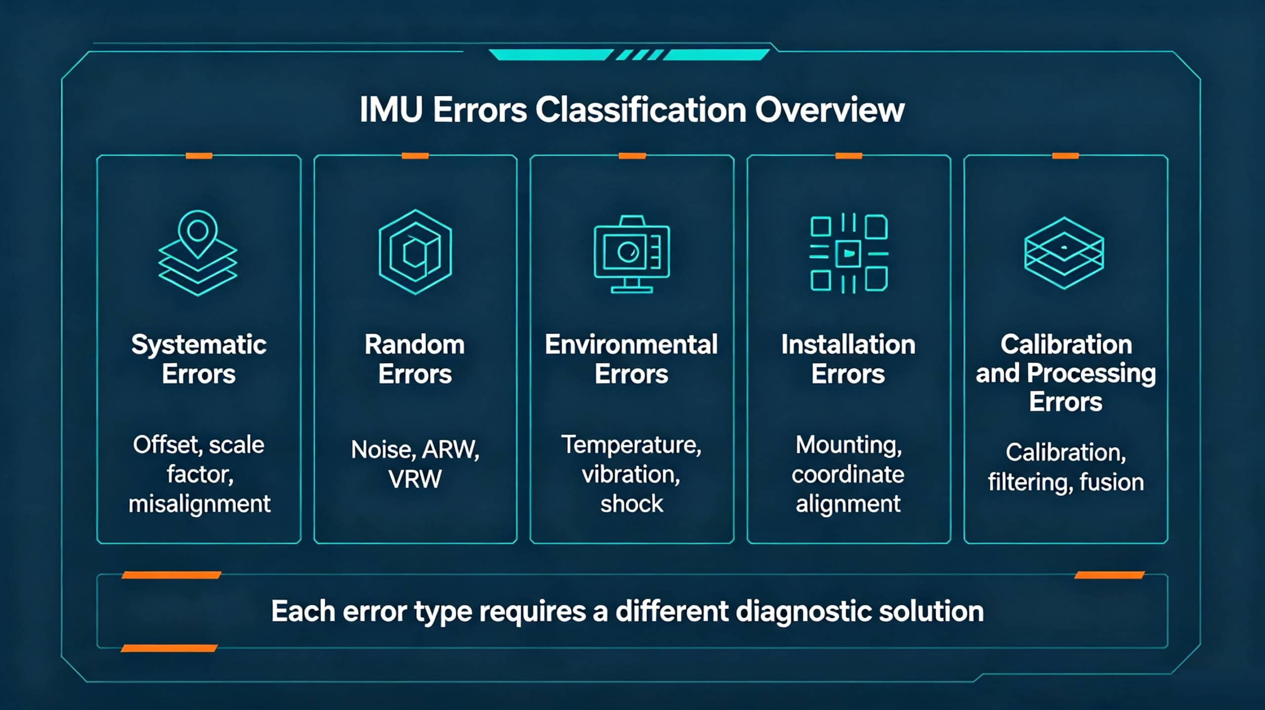
A useful way to classify IMU errors is into five categories:
- Systematic errors
- Random errors
- Environmental errors
- Installation errors
- Calibration and processing errors
Understanding this classification is important because each type requires a different solution.
For example, a stable gyroscope bias may require calibration or compensation, while vibration-induced noise may require better mechanical isolation or filtering.
Common IMU Errors at a Glance
| IMU Error | Typical Symptom | Common Cause |
|---|---|---|
| Gyroscope Bias | Attitude drift | Sensor offset |
| Accelerometer Bias | Velocity/position drift | Acceleration offset |
| Gyroscope Noise | Unstable angle output | Sensor noise |
| Accelerometer Noise | Noisy acceleration | Sensor noise |
| Scale-Factor Error | Proportional measurement error | Sensor characteristics |
| Misalignment Error | Cross-axis errors | Sensor structure or installation |
| Temperature Error | Performance changes with temperature | Thermal sensitivity |
| Vibration Error | Unstable or noisy output | Mechanical vibration |
| Calibration Error | Repeatable measurement offset | Incorrect calibration |
| Installation Error | Unexpected attitude/acceleration errors | Incorrect mounting or coordinate system |
This table provides a useful starting point for IMU troubleshooting, but identifying the actual problem requires looking at the sensor behavior under different test conditions.
Gyroscope Bias and Drift
What Is Gyroscope Bias?
Gyroscope bias is an offset in the gyroscope output when the actual angular rate is zero.
For example, imagine an IMU sitting completely still.
The ideal gyroscope output should be: 0 °/s
However, the sensor may report a small non-zero value.
That offset is bias.
It may remain relatively stable over a short period, but it can change with:
- Temperature
- Time
- Sensor aging
- Mechanical stress
- Vibration
- Power conditions
Why Does Gyroscope Bias Cause Drift?
Most attitude estimation systems obtain angular displacement by integrating angular velocity:
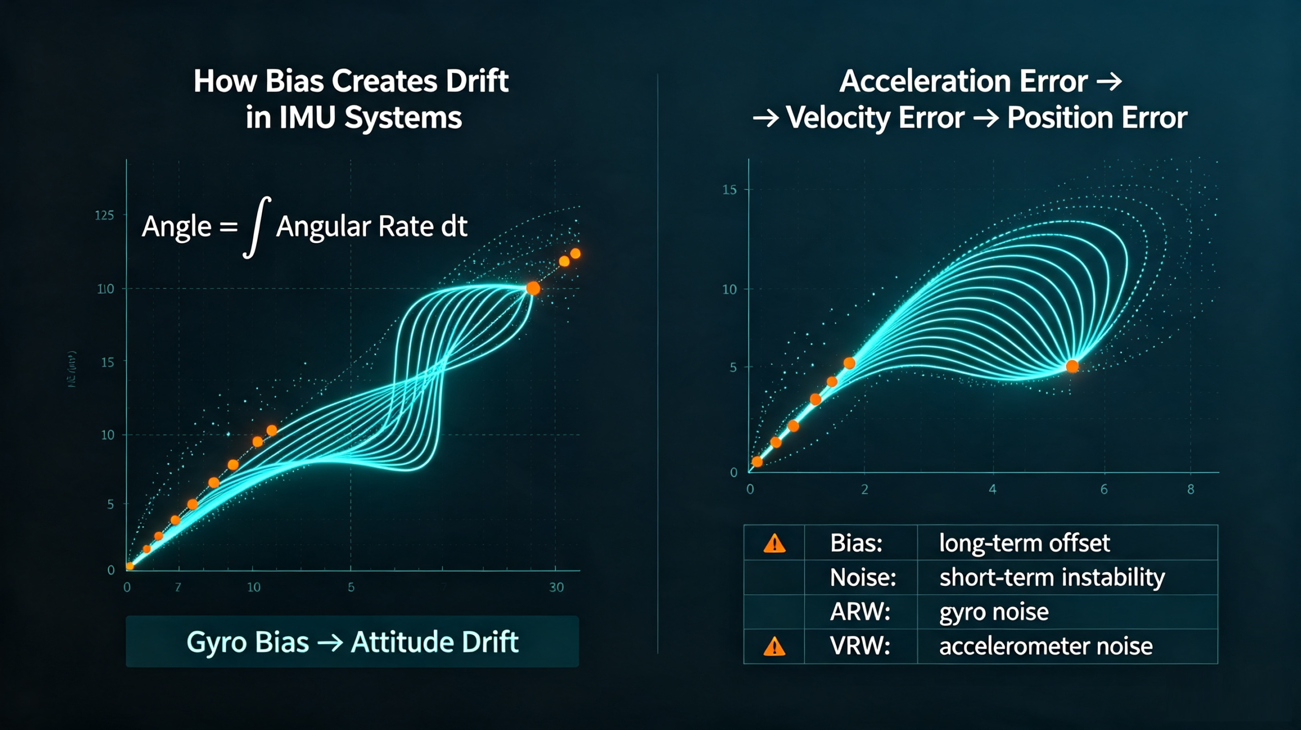
Angle = ∫ Angular Rate dt
Therefore, even a small persistent bias can accumulate over time.
This creates a phenomenon commonly referred to as gyroscope drift.
The effect is particularly important for:
- Inertial navigation
- UAVs
- Robotics
- Autonomous vehicles
- Marine navigation
- Mobile mapping
A sensor that appears accurate during a short static test may therefore show noticeable attitude drift during a long-duration test.
Accelerometer Bias and Position Drift
Gyroscope bias is not the only important IMU error.
Accelerometer bias can have an even greater impact on navigation.
An accelerometer measures specific force. If a constant acceleration error exists, integrating that error produces velocity error.
Further integration produces position error.
The simplified relationship is:
Acceleration Error → Velocity Error → Position Error
This is why accelerometer bias is particularly important for:
- INS
- Dead reckoning
- Mobile mapping
- Surveying
- Autonomous vehicles
- Long-duration navigation
A small acceleration error may not be obvious when viewing raw sensor data, but it can become significant after integration.
IMU Noise and Random Errors
Not every IMU error is a constant offset.
Sensor output also contains random variations.
For a gyroscope, this can appear as fluctuations around the actual angular rate.
For an accelerometer, it can appear as fluctuations around the actual acceleration.
These are commonly referred to as measurement noise.
Noise primarily affects short-term measurement quality and can lead to:
- Unstable attitude estimates
- Noisy acceleration data
- Control fluctuations
- Increased uncertainty
- Reduced navigation performance
Two important specifications are commonly used when characterizing inertial sensor noise:
Angle Random Walk (ARW)
ARW characterizes an important component of gyroscope noise.
Velocity Random Walk (VRW)
VRW characterizes an important component of accelerometer noise.
It is important not to confuse noise with bias.
| Error | General Behavior | Main Effect |
|---|---|---|
| Bias | Offset | Long-term drift |
| Noise | Random variation | Short-term instability |
| Scale Factor | Proportional error | Measurement accuracy |
| Misalignment | Axis coupling | multi-axis error |
This distinction is essential when diagnosing IMU measurement errors.
Scale-Factor Errors
A scale-factor error occurs when the sensor's output does not have the correct proportional relationship to the actual physical input.
For example, suppose a sensor is expected to report a particular angular rate but consistently reports a slightly higher or lower value.
The error is not simply an offset.
Instead:
Measured Value = Actual Value × Incorrect Scale Factor
Scale-factor errors can affect both gyroscopes and accelerometers.
They can become more apparent during dynamic testing, particularly when comparing sensor output against a known reference.
Calibration is normally required to characterize and compensate for these errors.
Axis Misalignment and Cross-Axis Errors
A three-axis IMU is designed to measure motion along three orthogonal axes.
Ideally:
- X measures X
- Y measures Y
- Z measures Z
In reality, the axes may not be perfectly orthogonal.
Small structural or installation misalignments can cause motion on one axis to influence measurements on another axis.
For example:
Motion on X → Small output on Y or Z
This is known as cross-axis sensitivity or misalignment-related error.
It can result from:
- MEMS sensor structure
- Manufacturing tolerances
- PCB alignment
- Mechanical mounting
- Incorrect coordinate transformation
For precision applications, these errors should be characterized and compensated through calibration.
Temperature-Related IMU Errors
Temperature is one of the most common environmental factors affecting MEMS IMU performance.
As temperature changes, sensor characteristics can change as well.
Potential effects include:
- Gyroscope bias variation
- Accelerometer bias variation
- Scale-factor changes
- Increased measurement uncertainty
- Changes in sensor noise
This means an IMU tested at room temperature may not provide exactly the same output under outdoor operating conditions.
This matters for:
- UAVs
- Autonomous vehicles
- Mining equipment
- Marine systems
- Industrial robots
- Outdoor navigation systems
Why Does Temperature Affect IMU Accuracy?
MEMS sensors contain mechanical structures and electronic components whose characteristics are temperature-dependent.
As a result, a sensor may have one bias value at 25°C and a different value at a significantly higher or lower temperature.
To reduce this effect, manufacturers may use:
- Temperature characterization
- Factory calibration
- Temperature compensation
- Software correction
- Multi-point calibration
When evaluating an industrial IMU, engineers should therefore look beyond nominal room-temperature specifications.
Vibration-Induced IMU Errors
Vibration is especially important for MEMS IMUs because many industrial systems contain moving or rotating components.
UAVs: Propellers and motors can transmit vibration through the airframe.
Robotics: Actuators and gearboxes can generate mechanical vibration.
AGVs and AMRs: Wheels and uneven surfaces can introduce vibration.
Mining Equipment: Heavy machinery can expose sensors to strong vibration and shock.
Industrial Equipment: Motors, pumps, fans, and rotating machinery can create continuous vibration. Vibration can increase measurement noise and introduce errors that are not visible during a static laboratory test.
How Can Vibration Errors Be Reduced?
Several approaches can help:
- Improve mechanical mounting.
- Place the IMU on a rigid structural reference.
- Avoid mounting close to strong vibration sources.
- Use appropriate mechanical isolation where required.
- Select an IMU designed for the expected environment.
- Apply suitable digital filtering.
- Verify the system through dynamic testing.
However, excessive filtering should be avoided because it can introduce latency and reduce dynamic response.
The correct solution is normally a combination of sensor selection + mechanical design + signal processing.
Calibration Errors
Even a high-performance IMU can produce inaccurate measurements if calibration is inadequate.
Typical calibration parameters include:
- Bias
- Scale factor
- Misalignment
- Nonlinearity
- Temperature dependency
For gyroscopes, calibration can characterize zero-rate output and scale-factor behavior.
For accelerometers, calibration can characterize bias, sensitivity, and axis alignment.
A proper calibration process can therefore significantly improve system-level performance.
IMU Installation Errors
Some apparent IMU sensor errors are actually installation problems.
Common examples include: Incorrect Orientation: The sensor axes do not match the system coordinate frame.
Loose Mounting: Mechanical movement between the sensor and platform introduces additional measurements.
Incorrect Coordinate Transformation: The software assumes a different sensor orientation than the physical installation.
Poor Mechanical Location: The sensor is mounted near a strong vibration source.
Cable or Mechanical Stress: Mechanical forces transmitted through the installation can affect measurements. This is why the installation should be considered part of the inertial measurement system not simply a packaging detail.
Static vs Dynamic IMU Errors
One of the most useful troubleshooting techniques is to compare IMU performance under static and dynamic conditions.
| Test | What It Can Help Identify |
|---|---|
| Static test | Bias and noise |
| Long-duration static test | Drift |
| Temperature test | Thermal sensitivity |
| Controlled rotation | Gyroscope performance |
| Linear acceleration test | Accelerometer response |
| Vibration test | Dynamic errors |
| Full-system test | Installation and integration problems |
Consider a situation where an IMU performs well while stationary but becomes unstable when installed on a UAV.
That suggests the problem may not be the basic static bias.
Instead, possible causes include:
- Propeller vibration
- Mechanical resonance
- Insufficient filtering
- Mounting problems
- Dynamic range limitations
- Control-loop interaction
This is why static specifications alone cannot fully predict real-world performance.
How to Troubleshoot IMU Errors
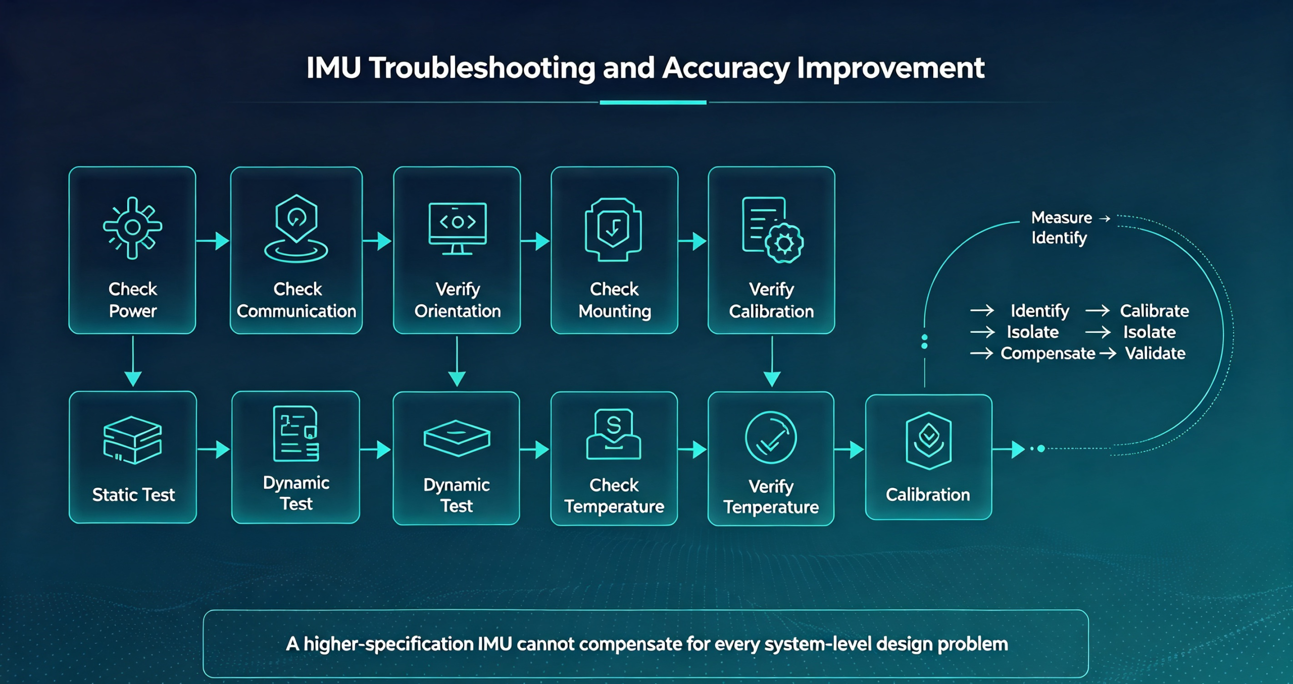
When an IMU produces unexpected results, a structured troubleshooting process is more effective than immediately replacing the sensor.
Step 1: Check the Power Supply
Verify that the sensor receives the specified voltage and that the power supply is stable.
Step 2: Check Communication
Confirm:
- Data integrity
- Baud rate
- Packet structure
- Output frequency
- Timestamp behavior
Step 3: Check Sensor Orientation
Verify the physical axis orientation against the software coordinate system.
Step 4: Check Mechanical Mounting
Make sure the sensor is rigidly and securely mounted.
Step 5: Perform a Static Test
Record the output while the sensor is completely stationary.
Look for:
- Bias
- Noise
- Stability
- Temperature dependence
Step 6: Perform a Dynamic Test
Evaluate the sensor under the actual motion conditions expected by the application.
Step 7: Check Temperature
Repeat the test under different temperatures if the application operates across a wide temperature range.
Step 8: Check Calibration
Verify whether calibration parameters are correct and whether the sensor has been calibrated for the intended application.
Step 9: Separate Sensor Errors From Algorithm Errors
Compare raw sensor output with processed output.
If the raw IMU data is reasonable but the navigation solution is incorrect, the problem may be related to:
- Filtering
- Sensor fusion
- Coordinate transformation
- Timing
- Integration algorithms
This distinction can save significant development time.
How to Improve IMU Accuracy
Improving IMU accuracy is normally a system-level task.
1. Improve Calibration
Characterize bias, scale factor, misalignment, and temperature behavior.
2. Reduce Vibration
Improve mechanical mounting and isolate the sensor from strong vibration sources when appropriate.
3. Control Temperature
Use thermal management or temperature compensation when required.
4. Select the Appropriate Measurement Range
Avoid sensor saturation while maintaining sufficient sensitivity.
5. Optimize Filtering
Use filtering appropriate to the application while maintaining acceptable latency.
6. Improve Mechanical Installation
Ensure the sensor is firmly attached and correctly aligned with the system coordinate frame.
7. Use Sensor Fusion
For applications requiring long-term navigation, combining IMU data with GNSS, magnetometers, odometry, visual sensors, or other external references can help control accumulated inertial errors.
The important principle is:
A better IMU can reduce sensor errors, but system design determines the final navigation performance.
How IMU Specifications Relate to Different Errors
When evaluating an IMU, each specification provides information about a different aspect of potential error.
| Specification | Potential Problem When Insufficient |
|---|---|
| Gyroscope Bias | Attitude drift |
| Accelerometer Bias | Velocity and position drift |
| ARW | Short-term angular noise |
| VRW | Velocity uncertainty |
| Measurement Range | Saturation |
| Bandwidth | Poor dynamic response |
| Temperature Stability | Thermal drift |
| Vibration Performance | Noisy dynamic output |
| Calibration | Systematic measurement error |
| Update Rate | Insufficient control response |
This is why engineers should not use a single specification as a substitute for complete IMU evaluation.
MEMS IMU Errors vs FOG IMU Errors
Both MEMS and FOG technologies can provide high-performance inertial measurements, but their characteristics differ.
| Characteristic | MEMS IMU | FOG IMU |
|---|---|---|
| Size | Compact | Generally larger |
| Weight | Low | Generally higher |
| Power | Low to moderate | Generally higher |
| Cost | Lower | Higher |
| Gyro stability | Application dependent | Generally excellent |
| Integration | Easy | More complex |
| UAV/robotics | Strong fit | Application dependent |
| High-end navigation | Application dependent | Strong fit |
MEMS IMUs are particularly attractive when size, weight, power, integration, and cost are important.
FOG-based systems become more attractive when the application requires very high long-term inertial stability.
The right choice depends on the actual error budget of the system.
ERICCO MEMS IMU Solutions
ERICCO develops MEMS and FOG inertial products for applications including UAVs, robotics, marine navigation, mining, surveying, oil and gas, aerospace, and industrial automation.
The company's MEMS IMU portfolio is designed for different levels of performance and integration requirements.
For example, the ER-MIMU-M02 is positioned as a compact MEMS inertial measurement solution for applications requiring integrated angular-rate and acceleration sensing.
ERICCO also provides higher-performance MEMS inertial solutions for applications such as mapping and precision measurement.
When evaluating an Ericco IMU, engineers should compare the actual specifications of each model, including:
- Gyroscope bias
- Accelerometer bias
- ARW
- VRW
- Measurement range
- Update rate
- Operating temperature
- Vibration and shock performance
- Communication interface
- Size and weight
This approach allows the sensor to be evaluated against the application's error budget rather than simply comparing product names.
Important: Exact performance values should always be confirmed against the latest product datasheet and configuration before procurement, as specifications may vary between models and customized configurations.
IMU Troubleshooting Checklist
When an IMU does not provide the expected performance, use the following checklist:
- Check power supply
- Check communication
- Verify sensor orientation
- Verify coordinate transformation
- Check mechanical mounting
- Check vibration
- Check operating temperature
- Perform a static test
- Perform a dynamic test
- Check gyroscope bias
- Check accelerometer bias
- Check noise
- Verify calibration
- Check filtering
- Check sensor-fusion algorithms
- Compare raw and processed data
This checklist can help determine whether the problem originates from the sensor, environment, installation, calibration, or software.
FAQ
Q: Why is my IMU drifting?
A: The most common causes include gyroscope bias, temperature changes, sensor noise, calibration errors, and accumulated integration errors.
For long-duration applications, even a small bias can become significant.
Q: Why is my IMU inaccurate?
A: An inaccurate output can result from the sensor itself, but it can also be caused by incorrect mounting, calibration, vibration, temperature, coordinate transformation, filtering, or navigation algorithms.
Q: What causes IMU errors?
A: Common causes include bias, noise, scale-factor errors, misalignment, temperature sensitivity, vibration, shock, installation problems, and calibration errors.
Q: How do I reduce IMU drift?
A: Start by characterizing gyroscope bias and temperature behavior. Proper calibration, stable mounting, temperature compensation, vibration reduction, and external sensor fusion can help reduce the effect of drift.
Q: Does temperature affect IMU accuracy?
A: Yes. Temperature can affect gyroscope bias, accelerometer bias, scale factor, and other sensor characteristics. Temperature compensation is therefore important for applications operating across wide temperature ranges.
Q: Can vibration affect an IMU?
A: Yes. Vibration can increase sensor noise and create dynamic measurement errors. This is especially important for UAVs, robots, AGVs, mining equipment, and machinery.
Q: How often should an IMU be calibrated?
A: There is no universal calibration interval. It depends on the sensor, application, operating environment, required accuracy, and manufacturer's recommendations.
Q: What causes accelerometer bias?
A: Accelerometer bias can result from sensor characteristics, temperature, manufacturing tolerances, mechanical stress, calibration errors, and aging.
Q: What causes gyroscope bias?
A: Gyroscope bias can be affected by sensor characteristics, temperature, mechanical stress, power conditions, aging, and calibration.
Q: Can a better IMU eliminate navigation errors?
A: Not completely. A higher-performance IMU can reduce sensor-related errors, but overall navigation performance also depends on calibration, installation, vibration, temperature, algorithms, timing, and external reference sensors.
Conclusion: Understanding IMU Errors Is as Important as Selecting the IMU
Understanding common IMU errors is essential for designing reliable inertial systems.
Gyroscope bias can cause attitude drift. Accelerometer bias can lead to velocity and position errors. Noise affects short-term stability, while scale-factor and misalignment errors can reduce measurement accuracy.
Environmental factors introduce another layer of complexity.
Temperature can change sensor characteristics. Vibration can increase measurement noise. Poor mounting or incorrect coordinate alignment can create errors that may initially appear to be sensor failures.
For this reason, improving IMU performance should not begin with simply replacing the sensor.
A better approach is:
Measure → Identify → Calibrate → Isolate → Compensate → Validate
The final performance of an inertial system depends on the entire chain:
Sensor + Calibration + Mechanical Design + Environment + Processing + Sensor Fusion
For industrial applications, MEMS IMUs provide an effective balance of size, weight, power consumption, integration, and performance. For applications requiring substantially higher inertial stability, FOG technology may be more appropriate.
If your project involves UAVs, robotics, AGVs, AMRs, autonomous vehicles, mapping, marine navigation, mining, or industrial automation, understanding the source of IMU errors can help you select the appropriate sensor and avoid unnecessary integration problems.
The goal is not simply to find an IMU with the highest specification. The goal is to build an inertial measurement system whose total error stays within the requirements of the application.