

Introduction
When developing unmanned aerial vehicles (UAVs), autonomous mobile robots (AMRs/AGVs), marine navigation systems, or industrial automation platforms, engineering teams frequently encounter two critical inertial sensing terms: IMU (Inertial Measurement Unit) and AHRS (Attitude and Heading Reference System).
At first glance, these devices appear remarkably similar. Both often utilize similar MEMS gyroscopes and accelerometers, share compact industrial enclosures, and support communication interfaces such as RS-232, RS-422, CAN, or UART. This overlap in external appearance and foundational hardware often leads engineers especially those new to inertial navigation to ask a fundamental question: Is an AHRS simply an IMU under a different name?
The answer is no.
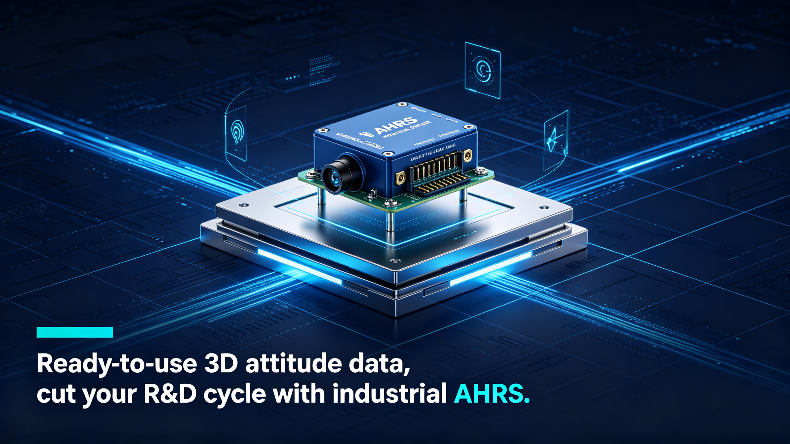
Although an AHRS is built upon the hardware foundation of an IMU, it is far more than just a collection of inertial sensors. An AHRS deeply integrates auxiliary sensors like magnetometers, advanced sensor fusion algorithms, and real-time attitude estimation systems to directly deliver ready-to-use orientation data to the end user.
Choosing the wrong device can significantly extend software development timelines, drive up algorithm R&D costs, or even limit the overall dynamic performance of your system. This article provides an in-depth engineering breakdown of the fundamental differences between an AHRS and an IMU across five key dimensions: hardware architecture, data output, fusion algorithms, typical application scenarios, and selection criteria. We will also use industrial-grade inertial navigation solutions (such as the ERICCO series) as practical examples to deliver a hands-on selection guide.
Common Misconceptions: Why Do Engineers Confuse AHRS and IMU?
One of the most common misconceptions in inertial navigation is that an AHRS and an IMU perform the exact same task. This confusion is completely understandable because both products share a substantial degree of internal hardware configuration.
For instance, a standard modern industrial-grade MEMS IMU typically contains:
-
Three-axis MEMS gyroscopes
-
Three-axis MEMS accelerometers
-
Full-temperature-range compensation circuitry
-
High-speed Digital Signal Processing (DSP) electronics
Meanwhile, a standard AHRS incorporates all the inertial hardware listed above, plus:
-
Three-axis MEMS magnetometers
-
Embedded sensor fusion processors
-
Real-time attitude estimation algorithms
-
Automatic heading (Yaw) correction modules
-
Dynamic motion compensation algorithms
In terms of external form factors, both devices may have identical dimensions, pin definitions, and interface protocols. However, from the perspective of information theory and control systems, their output data attributes are fundamentally different.
We can summarize the relationship using a straightforward engineering formula:
Clarifying this distinction is the first step for system architects designing a navigation solution: it directly dictates whether orientation algorithms must be developed in-house on the user's controller (such as an MCU, ROS, or SoC) or are already processed inside the inertial device's internal processor.
In-Depth Breakdown: What Is an IMU?
An IMU (Inertial Measurement Unit) is a physical sensing device that measures the motion state of an object by detecting inertial forces. Unlike GNSS/GPS receivers that rely on satellite signals, an IMU operates completely independently of external environments, measuring an object's angular velocity and linear acceleration continuously.
1. What Data Does an IMU Output?
An IMU does not directly output orientation angles (such as Roll, Pitch, or Yaw). Instead, it only outputs raw physical motion measurements that have not been processed through fusion algorithms:
-
Relative three-axis angular velocity ($^\circ/\text{s}$ or $\text{rad}/\text{s}$)
-
Relative three-axis linear acceleration ($\text{g}$ or $\text{m}/\text{s}^2$)
-
Internal sensor temperature data (for temperature compensation)
-
Hardware clock synchronization pulses and timestamp data
If a user needs to obtain the actual physical orientation of the platform, this raw data must be sent to an external host processor, where custom attitude estimation software (such as quaternion integration or Kalman filtering) computes the Roll, Pitch, Yaw, velocity, and position. Consequently, an IMU provides maximum system flexibility, but demands significant algorithm development expertise.
2. Evaluating Key Performance Parameters of Industrial IMUs
When evaluating or selecting an IMU, engineers should look beyond basic measurement ranges (such as $\pm300^\circ/\text{s}$ or $\pm10\text{g}$). In real-world engineering deployments, the following parameters dictate how quickly long-term orientation calculations will diverge:
| Performance Parameter | Engineering Significance (Why It Matters) |
| Gyroscope Bias Stability |
The core metric that determines long-term attitude drift. Lower bias stability results in slower integration divergence. |
| Angle Random Walk (ARW) |
Indicates short-term white noise levels, affecting small jitter in static orientation. |
| Accelerometer Bias Stability |
Directly impacts tilt estimation as well as velocity and position integration accuracy. |
| Data Update Rate |
Determines the real-time control loop response for high-dynamic platforms (e.g., high-speed UAVs). |
| Full-Temperature Calibration & Compensation |
The benchmark separating industrial-grade from consumer-grade products, ensuring data stability under drastic temperature changes. |
Senior Engineer Tip: When evaluating IMUs, do not focus solely on maximum range. In practical navigation algorithms, bias stability, temperature drift coefficients, and vibration rectification error (VRE) often exert a far greater influence on long-term navigation accuracy than the range itself.
In-Depth Breakdown: What Is an AHRS?
An AHRS (Attitude and Heading Reference System) is an intelligent orientation system built on top of inertial sensing technology. It not only measures motion but also "understands" it, calculating the absolute or relative 3D spatial orientation of the physical platform inside the device itself.
1. AHRS Hardware and Data Output
An AHRS typically integrates three-axis gyroscopes, three-axis accelerometers, three-axis magnetic sensors (magnetometers), and a high-performance embedded microprocessor.
After processing through its internal DSP or MCU, the AHRS outputs the following parameters directly to the main control system:
-
Roll Angle
-
Pitch Angle
-
Heading / Yaw Angle
-
Real-time three-axis angular rates and linear accelerations
-
System health status and data validity flags
Because orientation calculations run asynchronously at high frequencies inside the AHRS hardware, the main control system does not need to consume CPU computing power to handle heavy mathematical algorithms, dramatically lowering software development complexity.
2. How Sensor Fusion Solves Drift in an AHRS
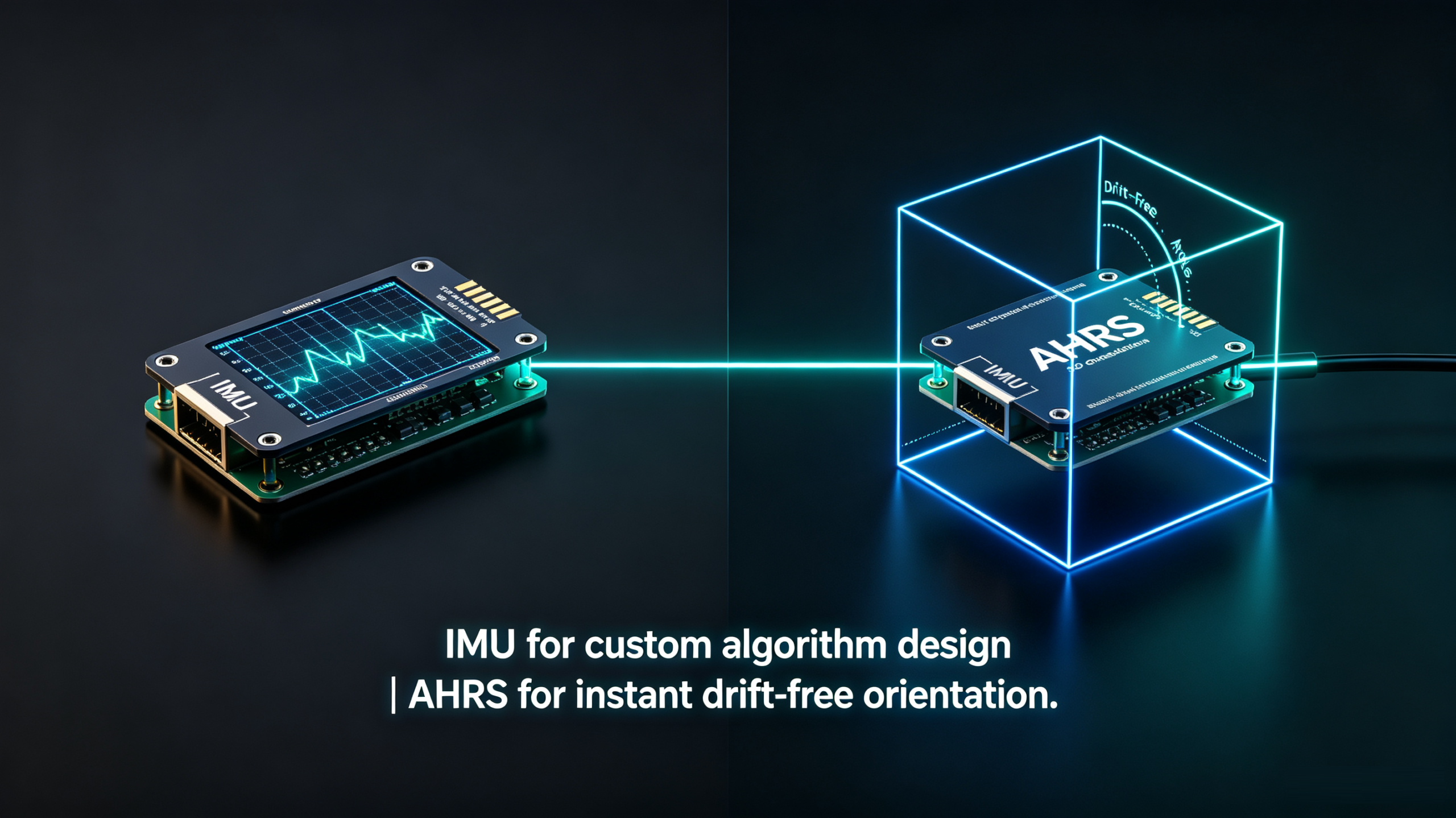
Individual sensors have inherent limitations: gyroscopes offer excellent short-term accuracy but suffer from severe cumulative drift over time; accelerometers sense gravity vectors but are susceptible to high-frequency vibration noise; magnetometers indicate magnetic north but are vulnerable to local magnetic interference.
The core strength of an AHRS lies in its embedded sensor fusion algorithms. Each sensor contributes specific capabilities to the fusion architecture:
┌────────────────┐
│ MEMS Gyroscope │ ──(Excellent short-term dynamic response)──┐
└────────────────┘ │
┌───────────────────┐ ▼
│ MEMS Accelerometer│ ──(Senses gravity, corrects Roll/Pitch drift)──► ┌──────────────────────────┐ ┌──────────────────────────────┐
└───────────────────┘ │ Embedded Sensor Fusion │ ──► │ Output Ready-to-Use 3D │
┌───────────────────┐ │ (EKF, Filter, etc.) │ │ Orientation │
│ MEMS Magnetometer │ ──(Senses magnetic field, corrects Heading drift)►└──────────────────────────┘ │ (Roll / Pitch / Heading) │
└───────────────────┘ ▲ └──────────────────────────────┘
Through internal Extended Kalman Filter (EKF) or complementary filter algorithms, the AHRS leverages accelerometers to correct long-term Roll and Pitch drift, while using magnetometers to correct Heading drift, delivering stable, continuous, non-divergent orientation solutions.
Hardware and Software Architecture Comparison: IMU vs. AHRS
To help system architects quickly identify technical selection boundaries, the following section compares the hardware architecture, software workload, and core features of both systems:
1. Data Flow and Computing Allocation
-
IMU Minimalist Data Flow:
Hardware (Gyros + Accels) → Output RAW Data → [Transmit to Host] → Host Runs Fusion Algorithm → Calculates Roll/Pitch/Heading -
AHRS Internal Closed-Loop Data Flow:
Hardware (Gyros + Accels + Mags) → [Internal DSP Runs EKF] → Outputs Roll/Pitch/Heading Directly
2. Software Workload Comparison
| Development / Integration Task | Using an IMU | Using an AHRS |
| Read raw physical data via Serial/CAN |
✔ |
✔ |
| Sensor bias and calibration matrix compensation |
Must be developed by user
|
Factory calibrated
|
| Three-axis magnetometer hard/soft iron calibration |
Must be developed by user
|
Factory / Built-in algorithms
|
| Kalman Filter (EKF) state formulation and tuning |
Must be developed by user
|
Built-in, zero development
|
| Real-time Roll / Pitch angle calculation |
Must be developed by user
|
Directly read solution
|
| Real-time absolute Heading correction |
Must be developed by user
|
Directly read solution
|
| Overall R&D Development Cycle |
Longer (Months)
|
Extremely Short (Days)
|
Application Selection Guide: Which Is Right for Your Project?
In practical engineering projects, there is no single "better" device only the solution that best matches your application requirements and software engineering capacity. Based on real-world engineering deployments, here are selection recommendations across typical industries:
1. UAV Flight Control Systems
-
Recommended Solution: AHRS
-
Selection Rationale: Modern UAVs (multirotors, VTOL aircraft, fixed-wing drones) demand real-time stability during flight maneuvers. An AHRS outputs stable, drift-free attitude angles that flight control microcontrollers can instantly feed into PID control loops, significantly reducing product time-to-market.
2. Industrial Robotics and AGVs/AMRs
-
Recommended Solution: AHRS
-
Selection Rationale: Warehouse AGVs, inspection robots, and agricultural machinery require accurate motion planning and balance control. Robotics companies that lack dedicated navigation algorithm teams can use an AHRS to bypass complex low-level math and achieve rapid self-balancing and path tracking.
3. Autonomous Vehicles and Heavy Machinery
-
Recommended Solution: High-Performance IMU + GNSS Integrated Solution (INS)
-
Selection Rationale: Autonomous vehicles require more than orientation they need centimeter-level absolute position and precise linear velocity. In these architectures, engineers prefer low-bias IMUs and integrate raw inertial measurements with multi-frequency GNSS (RTK) and wheel speed odometry inside deep or tight-coupling Kalman filtering frameworks.
4. Marine Engineering and Unmanned Surface Vessels (USVs)
-
Recommended Solution: High-Protection Industrial AHRS
-
Selection Rationale: Marine environments present challenging conditions, including continuous wave motion (causing rapid Roll and Pitch oscillations) and severe magnetic disturbances. An industrial AHRS equipped with dynamic vibration rejection and magnetic compensation algorithms delivers dependable heading and attitude references for USV dynamic positioning and radar stabilization.
5. High-Precision Surveying and Mapping
-
Recommended Solution: Navigation-Grade IMU / High-End INS
-
Selection Rationale: Airborne LiDAR scanning and hydrographic surveying require extreme attitude precision, where even a $0.01° orientation error can create massive position distortions at long ranges. These systems generally pair fiber-optic or high-precision MEMS IMUs with RTK-GNSS for real-time or post-processed positioning.
Case Studies and Industrial Product Breakdown (The ERICCO Perspective)
To help ground technical selection in practical engineering, we can compare mature industrial IMU and AHRS product profiles (using the ERICCO inertial product line as an example).
1. A Real-World Engineering Case
A UAV manufacturer initially selected a standard MEMS IMU for flight control board integration. During development, the engineering team spent nearly four months working through gyroscope temperature drift, magnetometer interference, and Extended Kalman Filter (EKF) convergence issues, causing severe project delays.
The team eventually switched to an industrial-grade AHRS. Because the AHRS handled sensor calibration and Kalman filtering internally, the flight controller received accurate Roll, Pitch, and Heading data over the CAN bus immediately. System integration was simplified, development delays were resolved, and overall flight stability improved markedly.
2. Representative Product Specifications
-
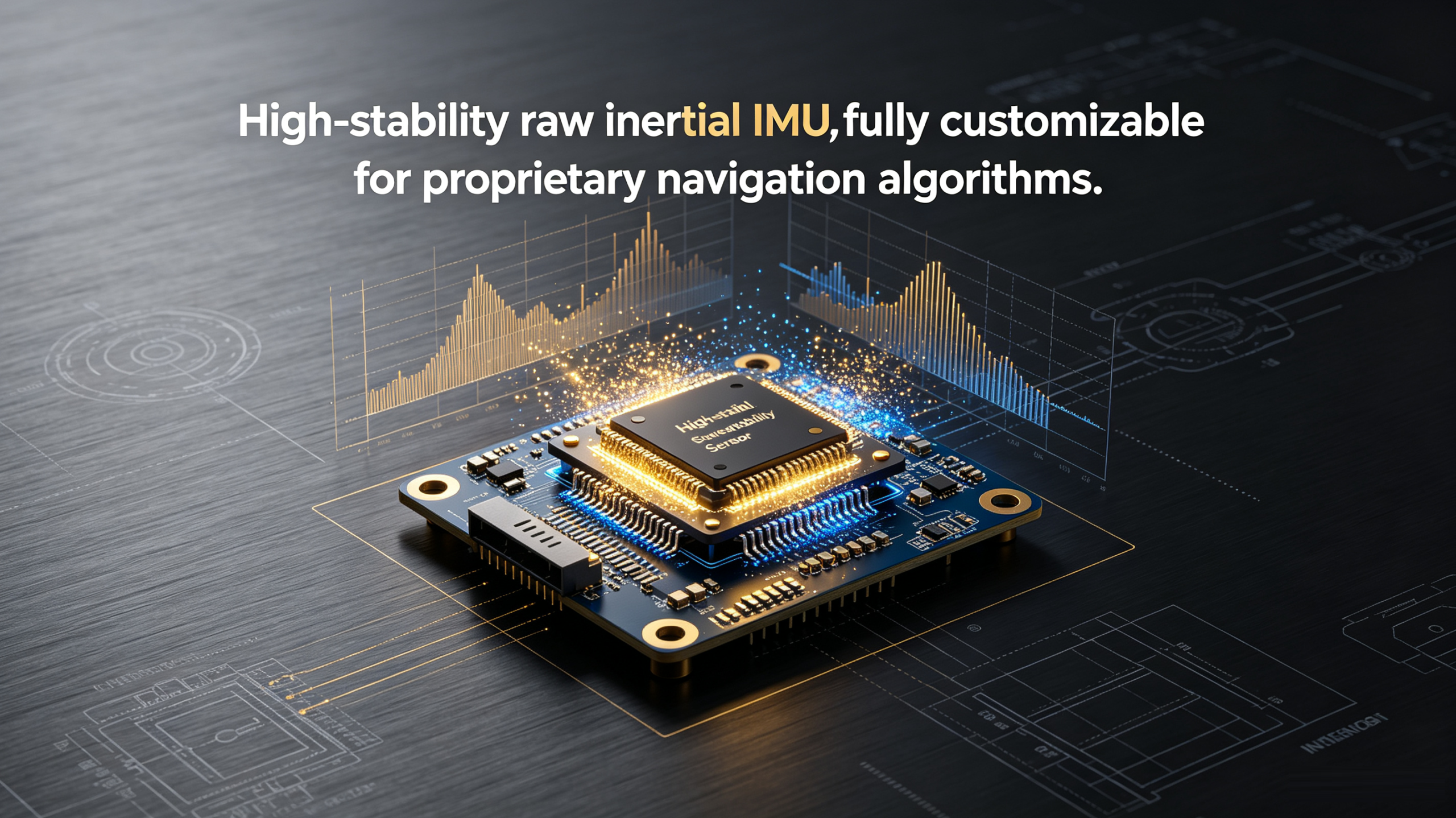
ERICCO MEMS IMU Series: Tailored for customers with proprietary algorithm development capability, offering ultra-compact sizes, low power consumption, high sampling rates, and exceptional full-temperature bias stability. Widely deployed in autonomous driving GNSS/INS platforms, motion capture systems, and research platforms.
-
ER-AHRS-5 (High-Precision Industrial AHRS):
-
Roll/Pitch Accuracy: Up to $0.3°
-
Heading Accuracy: Better than $0.5°
-
Update Frequency: Up to 200 Hz
-
Operating Temperature: $-40℃+80℃
-
Communication Interfaces: RS-232 / RS-422 / CAN (configurable)
-
Typical Applications: High-end UAV navigation, marine radar stabilization, antenna tracking, mobile robotics.
-
-
ER-AHRS-7 (Cost-Effective Industrial AHRS): Delivers an optimal balance of cost and performance in a compact footprint, providing dependable attitude solutions for commercial UAVs, warehouse AGVs, educational robotics, and industrial automation equipment.
Engineering Selection Checklist
Before ordering inertial hardware from a manufacturer, system engineers should evaluate the following questions:
-
Accuracy Requirements
-
Have you defined the minimum dynamic accuracy needed for Roll/Pitch (e.g., $<0.5°)?
-
Does your application require strict absolute heading accuracy with magnetic field immunity?
-
-
Stability & Dynamics
-
Does the gyroscope bias stability satisfy requirements during periods without external aiding updates?
-
Can the output update frequency (e.g., 200Hz/400Hz) match your real-time control loop timing?
-
-
Environmental Conditions
-
Does the operating temperature range (e.g., $-40℃ ∽ +80℃) cover your operational environment?
-
Will the device experience severe high-frequency vibration? Is mechanical shock isolation required?
-
-
Software & Integration Resources
-
Does your R&D team have dedicated navigation algorithm engineers to write EKF and calibration code? (No → Choose AHRS; Yes → Consider IMU)
-
Are the communication interfaces (RS-232/CAN/UART) and protocols compatible with your current hardware architecture?
-
FAQ
Q1: Can an AHRS completely replace an IMU?
A: Not in a conceptual sense. An AHRS internally contains an IMU, it is essentially an "upgraded and fully encapsulated functional version" of an IMU. If you require raw motion data to develop custom algorithms, buy an IMU. If you need ready-to-use attitude angles, an AHRS is the ideal choice.
Q2: Can an IMU calculate Roll and Pitch directly via numerical integration?
A: In theory, angles can be computed by integrating angular velocity over time. However, due to gyroscope bias drift, integrated angles diverge rapidly, making them unusable for real-world control without correction. Accelerometer data (gravity vectors) must be fused using Kalman filtering to suppress drift which is precisely what an AHRS performs automatically.
Q3: Why are AHRS units typically more expensive than standalone IMUs?
A: An AHRS incorporates additional magnetometer sensors, higher-performance embedded processing hardware, factory multi-temperature multi-axis rotation table calibration, and embedded proprietary sensor fusion algorithms.
Q4: Does an AHRS require GPS/GNSS signals to operate?
A: No. An AHRS is an entirely self-contained attitude reference system that computes orientation and heading using only internal inertial and magnetic sensors, making it immune to GPS jamming or signal outages.
Conclusion
Although an AHRS and an IMU share a similar MEMS hardware base, they are engineered to solve distinctly different engineering problems.
-
Choose an IMU: When you demand complete customization flexibility, possess a dedicated navigation algorithm team, or are building complex GNSS/INS tightly coupled navigation systems, an IMU serves as the ideal foundation for high-quality raw data.
-
Choose an AHRS: When your goal is to shorten R&D integration cycles, reduce host MCU computational loads, and obtain plug-and-play 3D orientation data, an AHRS offers the most efficient engineering path.
By evaluating your application constraints and software development capacity, selecting the right inertial solution such as ERICCO industrial MEMS IMU or AHRS product lines will ensure your project performs reliably and reaches the market on schedule.