

Quick Answer
A MEMS IMU for autonomous vehicles provides high-rate measurements of angular velocity and acceleration, helping an autonomous platform estimate its attitude and motion in real time. Unlike GNSS, an IMU does not depend on satellite signals, making it useful when positioning signals are blocked or temporarily unavailable.
However, an IMU is not a complete replacement for GNSS or other navigation sensors. Its measurements accumulate error over time, so modern autonomous systems typically combine IMU data with GNSS, wheel odometry, LiDAR, cameras, magnetometers, or other sensors through sensor-fusion algorithms.
For AGVs, AMRs, autonomous vehicles, and other unmanned platforms, the right MEMS IMU can provide the high-frequency motion information needed for navigation, stabilization, localization, and control.
Why Do Autonomous Vehicles Need an IMU?
Autonomous vehicles must continuously answer several basic questions:
- Where am I?
- Which direction am I moving?
- How fast am I moving?
- Am I turning, accelerating, or braking?
- Has the vehicle changed its orientation?
- Where will I be a few moments from now?
No single sensor can answer all of these questions reliably under every operating condition.
GNSS can provide absolute position and velocity information, but satellite signals can be blocked or degraded in tunnels, underground environments, urban canyons, and other challenging locations. Cameras can provide valuable visual information but may be affected by lighting, weather, visibility, and scene characteristics. LiDAR provides detailed environmental information but adds system complexity and depends on the surrounding environment.
An IMU provides a different type of information.
It measures motion itself.
By measuring angular velocity and acceleration at a high rate, an IMU gives the navigation system a continuous stream of inertial information. This makes it an important complementary sensor for autonomous navigation.
ERICCO similarly describes MEMS IMUs as complementary to external navigation sources, particularly where GNSS and other sensors can encounter environmental limitations.

What Does an IMU Measure on an Autonomous Vehicle?
A typical six-axis IMU integrates:
- Three-axis gyroscopes
- Three-axis accelerometers
The gyroscopes measure angular velocity around the X, Y, and Z axes.
The accelerometers measure specific force along those axes.
Together, these measurements provide information about changes in the vehicle's motion and orientation.
Gyroscope Measurements
Gyroscope data is particularly important for determining changes in:
- Roll
- Pitch
- Yaw
- Turning rate
- Angular motion
For an autonomous ground vehicle, this information can help the system understand when the vehicle begins turning or changes its heading.
For an aerial vehicle, the same measurements are essential for flight stabilization and attitude control.
Accelerometer Measurements
Accelerometer data provides information about linear motion and changes in acceleration.
It can contribute to:
- Velocity estimation
- Dead reckoning
- Motion detection
- Vehicle control
- Navigation-state estimation
However, acceleration must normally be integrated over time to estimate velocity and position. This means even small accelerometer errors can accumulate.
That is why IMU accuracy is not determined by one specification alone.
How an IMU Supports Autonomous Vehicle Navigation
The role of an IMU in an autonomous vehicle can be simplified into four stages:
Motion → Measurement → Sensor Fusion → Navigation State
The IMU continuously measures the vehicle's motion.
The navigation system then combines those measurements with information from other sensors to estimate:
- Position
- Velocity
- Attitude
- Heading
- Motion state
This information can then be provided to the vehicle's:
- Navigation system
- Path planner
- Motion controller
- Stabilization system
- Obstacle-avoidance system
The IMU therefore functions as a fundamental motion-sensing layer rather than simply being another positioning sensor.
IMU + GNSS: Why Sensor Fusion Matters
One of the most common architectures for autonomous navigation is the combination of an IMU and GNSS.
The two technologies have complementary strengths.
| Sensor | Main Strength | Main Limitation |
|---|---|---|
| GNSS | Absolute position and velocity reference | Signal blockage or degradation |
| IMU | High-rate motion measurement | Accumulated drift |
| Wheel Encoder | Vehicle-relative motion | Wheel slip and mechanical errors |
| LiDAR | Environmental perception and mapping | Cost and environmental dependence |
| Camera | Visual perception | Lighting and visibility limitations |
GNSS can provide a long-term position reference, while the IMU provides high-rate motion information between external updates.
This is one reason IMU GNSS integration is widely used in inertial navigation systems.
The basic concept is:
GNSS → Long-term reference
IMU → Short-term motion continuity
When GNSS measurements are available, they can help constrain accumulated inertial error. Between GNSS updates, the IMU can continue providing motion information.
This complementary architecture is more robust than relying entirely on either sensor.
What Happens When GNSS Is Lost?
GNSS-denied navigation is one of the most important reasons to use an IMU.
Consider an autonomous vehicle entering:
- A tunnel
- Underground parking
- A warehouse
- A dense urban area
- A mine
- A partially enclosed industrial environment
The GNSS signal may become unavailable or unreliable.
The IMU does not suddenly stop measuring motion.
It continues measuring angular velocity and acceleration.
This enables the navigation system to continue estimating the vehicle's motion for a period of time.
However, there is an important limitation:
An IMU does not provide unlimited drift-free navigation without external references.
Gyroscope and accelerometer errors accumulate through integration. The longer the system operates without correction, the greater the potential position and attitude error.
Therefore, a practical autonomous navigation system should determine:
- How long GNSS outages may last.
- How much position error is acceptable.
- How much attitude error is acceptable.
- What other sensors can provide correction.
- What IMU performance is required for the expected outage period.
This is a much more realistic approach than assuming an IMU can simply replace GNSS.
MEMS IMU for AGV Navigation
Automated Guided Vehicles, or AGVs, operate in environments where reliable motion information is essential.
Typical applications include:
- Warehouses
- Manufacturing plants
- Logistics centers
- Industrial facilities
- Automated material handling
An IMU for AGV navigation can provide information about:
- Heading changes
- Vehicle acceleration
- Turning motion
- Vehicle attitude
- Short-term motion between external positioning updates
AGVs can also combine IMU data with wheel encoders.
For example:
Wheel Encoder + IMU
The wheel encoder provides information about wheel movement, while the IMU provides independent angular and acceleration measurements.
This can help the system detect inconsistencies caused by:
- Wheel slip
- Uneven surfaces
- Mechanical differences
- Rapid vehicle motion
MEMS IMU for AMR Navigation
Autonomous Mobile Robots, or AMRs, operate differently from traditional fixed-route AGVs.
AMRs may need to:
- Select routes dynamically
- Avoid obstacles
- Navigate changing environments
- Localize themselves continuously
- Integrate multiple perception sensors
This makes sensor fusion particularly important.
An IMU for AMR can provide high-frequency motion information between updates from other sensors.
For example, an AMR might combine:
IMU + LiDAR + Wheel Odometry + Camera
Each sensor contributes different information.
The IMU provides motion continuity.
LiDAR provides environmental geometry.
The camera provides visual information.
Wheel odometry provides vehicle-specific movement constraints.
Together, these sources can produce a more robust estimate of the robot's state than any individual sensor.
MEMS IMU for Autonomous Vehicles vs. Traditional Inertial Systems
MEMS technology has changed the practicality of deploying inertial sensors across large numbers of autonomous platforms.
Compared with larger and more expensive traditional inertial systems, MEMS IMUs generally offer advantages in:
| Characteristic | MEMS IMU | Traditional High-End Inertial System |
|---|---|---|
| Size | Compact | Generally larger |
| Weight | Low | Generally higher |
| Power | Low to moderate | Generally higher |
| Cost | More scalable | Higher |
| Integration | Easier | More complex |
| Mass deployment | Well suited | Less economical |
| Application flexibility | High | Application dependent |
This is particularly important for autonomous systems.
An autonomous vehicle may require several sensing technologies simultaneously. If the inertial sensor is too large, heavy, power-hungry, or expensive, it can make the overall system more difficult to design.
MEMS IMUs can therefore provide an attractive balance between performance, integration, and cost.
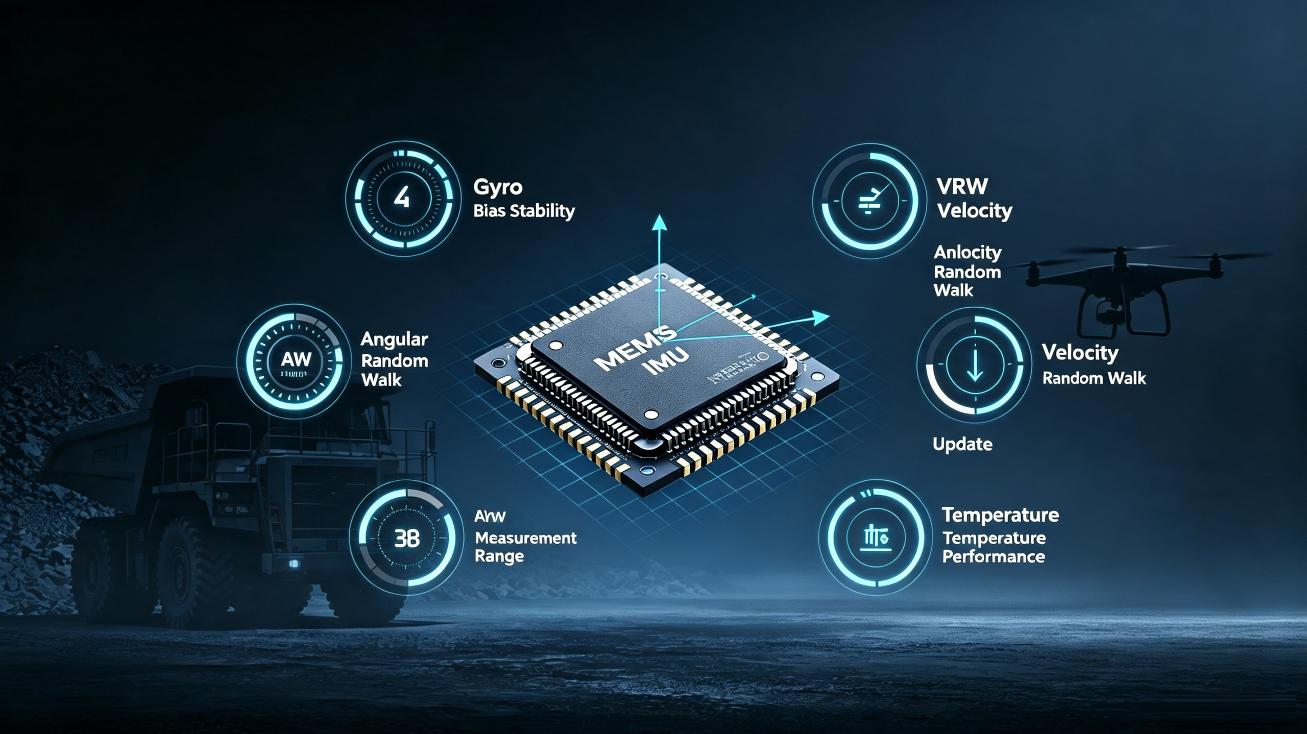
What IMU Specifications Matter for Autonomous Vehicles?
Not every autonomous vehicle requires the same IMU.
A slow indoor AMR, a high-speed autonomous vehicle, and a heavy mining vehicle may have very different inertial requirements.
The following specifications deserve particular attention.
| Specification | Why It Matters |
|---|---|
| Gyroscope Bias | Affects long-term attitude and heading stability |
| Accelerometer Bias | Affects velocity and position estimation |
| ARW | Indicates an important component of gyro noise |
| VRW | Indicates an important component of accelerometer noise |
| Measurement Range | Determines how much motion can be measured before saturation |
| Update Rate | Affects real-time control and state estimation |
| Bandwidth | Determines dynamic response |
| Temperature Performance | Important for changing outdoor conditions |
| Vibration Performance | Important for vehicles and machinery |
| Interface | Determines system integration requirements |
Gyroscope Bias
For autonomous navigation, gyroscope bias is particularly important because angular-rate errors accumulate through integration.
A lower bias generally supports better long-term attitude stability, assuming other error sources are controlled.
Accelerometer Bias
Accelerometer bias can accumulate into velocity and position errors.
This becomes especially important when the vehicle experiences long periods without an external positioning update.
Angular Random Walk
Angular Random Walk, or ARW, is an important indicator of gyroscope noise behavior.
It helps engineers understand short-term angular measurement stability.
Velocity Random Walk
VRW characterizes an important component of accelerometer noise and is relevant when evaluating velocity estimation performance.
How Does an IMU Work With Other Autonomous Vehicle Sensors?
An autonomous vehicle can use an IMU as part of a larger multi-sensor architecture.
IMU + GNSS
Best suited for applications requiring continuous navigation with an absolute position reference.
Strength: Position reference + high-rate inertial data.
IMU + LiDAR
Useful for mapping and localization.
Strength: Motion estimation + environmental geometry.
IMU + Camera
Commonly associated with visual-inertial navigation.
Strength: Motion sensing + visual features.
IMU + Wheel Encoder
Particularly useful for AGVs and wheeled robots.
Strength: Inertial motion + vehicle-specific motion constraints.
IMU + GNSS + LiDAR + Camera
A more comprehensive architecture can combine:
Absolute Position + Inertial Motion + Environmental Perception + Visual Information
The key point is that the IMU does not need to perform every navigation function by itself.
Instead, it can provide a high-rate inertial reference that helps connect information from multiple sensors.
Common Challenges When Integrating an IMU Into an Autonomous Vehicle
Selecting the correct IMU is only the first step.
System integration can introduce additional errors.
1. Incorrect Coordinate Alignment
The IMU coordinate system must be correctly related to the vehicle coordinate system.
If the software assumes the wrong orientation, even accurate sensor data can produce incorrect navigation results.
2. Poor Mechanical Mounting
A loose or flexible mounting structure can introduce motion that the IMU interprets as vehicle movement.
3. Vibration
Motors, wheels, gearboxes, engines, and other mechanical components can introduce vibration.
This can increase measurement noise and complicate sensor fusion.
4. Timing and Synchronization
Sensor data must be correctly timestamped.
Even accurate measurements can become problematic if GNSS, camera, LiDAR, wheel encoder, and IMU data are not properly synchronized.
5. Calibration
Bias, scale factor, and alignment errors must be considered.
6. Temperature
Outdoor autonomous vehicles may experience substantial temperature changes.
Therefore, temperature compensation can be an important part of system design.
How to Select a MEMS IMU for an Autonomous Vehicle
Rather than choosing an IMU based only on its highest specification, engineers should begin with the vehicle's actual operating requirements.
Step 1: Define Vehicle Dynamics
Determine:
- Maximum angular rate
- Maximum acceleration
- Expected vibration
- Maximum speed
- Turning behavior
This determines the required measurement range.
Step 2: Define Navigation Accuracy
Determine the acceptable:
- Attitude error
- Heading error
- Velocity error
- Position drift
This establishes the required inertial performance.
Step 3: Define Environmental Conditions
Consider:
- Temperature
- Vibration
- Shock
- Humidity
- Installation conditions
Step 4: Define Sensor-Fusion Architecture
Determine whether the IMU will work with:
- GNSS
- LiDAR
- Camera
- Wheel encoder
- Magnetometer
- Barometer
Step 5: Define Mechanical and Electrical Requirements
Check:
- Size
- Weight
- Power consumption
- Interface
- Mounting
- Data rate
Step 6: Select the Appropriate Performance Level
The objective is not:
“Find the most accurate IMU.”
It is:
“Find an IMU whose total performance matches the vehicle's error budget.”

ERICCO MEMS IMU Solutions for Autonomous Applications
ERICCO offers MEMS inertial products covering different performance and integration requirements for applications including autonomous machines, unmanned vehicles, robotics, UAVs, mapping, and navigation.
One example is the ER-AMM-M02 High Performance MEMS IMU.
According to its current product information, the ER-MIMU-M02 provides a three-axis digital gyroscope with a ±450°/s dynamic measurement range, 2°/h gyroscope bias instability, and 0.15°/√h angular random walk. Its three-axis digital accelerometer has a 16 g dynamic measurement range and 24 μg bias instability. The unit also incorporates temperature calibration and compensation for operation across -40°C to 80°C.
These specifications make the ER-MIMU-M02 relevant when an autonomous platform requires a combination of compact inertial sensing, dynamic response, and temperature adaptability.
ERICCO also offers the ER-MIMU-063, previously designated ER-MIMU-07. Its published specifications include a 400°/s gyroscope range, less than 0.3°/h gyroscope bias instability, less than 0.125°/√h angular random walk, and a 30 g accelerometer range. The product is explicitly listed for robotic control and orientation in autonomous machines and unmanned vehicles, as well as GNSS-assisted INS applications.
For more cost-sensitive attitude-control applications, the ER-MIMU-104 provides a ±400°/s gyroscope range, 1°/h bias instability, 0.2°/√h angular random walk, and 30 g accelerometer range, with temperature compensation across -40°C to 80°C.
These examples illustrate why IMU selection should be based on the actual requirements of the autonomous platform rather than a single headline specification.
MEMS IMU Requirements for Different Autonomous Platforms
Different platforms have different priorities.
| Platform | Main IMU Requirement |
|---|---|
| AGV | Heading and motion stability |
| AMR | Navigation and sensor fusion |
| Delivery Robot | Compact size and low power |
| Autonomous Vehicle | Navigation stability and dynamic response |
| Mining Vehicle | Environmental robustness |
| UAV | High dynamic response and low weight |
| Mobile Robot | Compact integration and low drift |
For example, an indoor AMR may prioritize compact dimensions, low power consumption, and reliable sensor fusion.
A mining vehicle may place greater emphasis on vibration, temperature, shock, and long-term stability.
A high-speed autonomous platform may require a higher measurement range and sufficient bandwidth to capture rapid vehicle dynamics.
This is why there is no universal “best IMU for autonomous vehicles.”
The best choice depends on the application.
Can a MEMS IMU Replace GNSS?
Generally, no—not for long-duration absolute navigation.
An IMU measures inertial motion, while GNSS provides an external position and timing reference.
Without correction, inertial errors accumulate.
The more useful question is:
How can MEMS IMU and GNSS work together?
A GNSS/INS architecture can use GNSS to constrain long-term drift while using the IMU to provide high-rate motion information between GNSS updates.
For short GNSS outages, a suitable IMU can therefore help maintain navigation continuity.
For longer outages, the required IMU performance becomes increasingly demanding.
This distinction is critical when designing autonomous navigation systems.
FAQ
Q: What does an IMU do in an autonomous vehicle?
A: An IMU measures angular velocity and acceleration to provide high-rate information about vehicle motion and orientation. Its data can be combined with GNSS, LiDAR, cameras, wheel encoders, and other sensors for navigation and control.
Q: Does an autonomous vehicle need an IMU?
A: Many autonomous navigation architectures benefit significantly from an IMU because it provides continuous high-rate motion measurements and complements positioning and perception sensors.
Q: Does an IMU replace GPS?
A: No. An IMU can continue providing inertial measurements when GNSS is unavailable, but its errors accumulate over time. In many systems, IMU and GNSS are complementary technologies.
Q: What is the best IMU for autonomous vehicles?
A: There is no universal best IMU. The appropriate sensor depends on required accuracy, measurement range, bias stability, noise, temperature range, vibration environment, size, power, and system architecture.
Q: Why is an IMU important for AGVs?
A: An IMU can provide heading and motion information that complements wheel odometry and other localization technologies, helping AGVs maintain reliable motion estimation.
Q: Why do AMRs use IMUs?
A: AMRs operate in dynamic environments and often integrate LiDAR, cameras, wheel encoders, and other sensors. An IMU provides high-rate motion information that can support localization and sensor fusion.
Q: Can a MEMS IMU be used for autonomous navigation?
A: Yes. MEMS IMUs are widely applicable to autonomous navigation when their performance is matched to the vehicle's dynamics, environmental conditions, and navigation requirements.
Q: How does an IMU work with LiDAR?
A: The IMU provides inertial motion information while LiDAR provides environmental geometry. Their data can be combined for localization, mapping, and motion estimation.
Q: How does an IMU work with a camera?
A: An IMU provides motion measurements while the camera provides visual information. Combining them can support visual-inertial navigation and improve motion estimation when visual information is available.
Q: How long can an IMU navigate without GNSS?
A: There is no universal time limit. The duration depends on gyroscope and accelerometer errors, calibration, vehicle dynamics, external corrections, and the maximum acceptable navigation error.
Conclusion: Why MEMS IMUs Matter for Autonomous Vehicles
Autonomous navigation requires more than one sensor.
GNSS provides an external positioning reference. Cameras and LiDAR provide environmental information. Wheel encoders provide vehicle-specific motion information. A MEMS IMU provides something different: continuous, high-rate measurement of inertial motion.
That makes a MEMS IMU for autonomous vehicles an important component of modern sensor-fusion architectures.
For AGVs and AMRs, an IMU can complement wheel odometry and LiDAR-based localization. For autonomous vehicles, it can work with GNSS and other sensors to maintain motion estimates and improve navigation continuity. In GNSS-challenged environments, it can continue providing inertial measurements even when external positioning information is temporarily unavailable.
But an IMU is not a magic solution.
Its performance is influenced by:
Sensor quality + calibration + mounting + temperature + vibration + timing + algorithms + sensor fusion
The right approach is therefore not to search for the highest specification in every category.
Instead, engineers should define the vehicle's dynamics, navigation accuracy, environment, sensor-fusion architecture, and integration requirements first.
Then they can select a MEMS IMU whose performance fits the system's actual error budget.
For autonomous vehicles, AGVs, AMRs, robotics, UAVs, mining equipment, and other unmanned platforms, this approach can provide a practical balance between accuracy, size, power consumption, integration complexity, and cost.
ERICCO's MEMS IMU portfolio provides different performance levels for these applications, from compact and cost-conscious inertial sensing to higher-performance solutions for demanding navigation and control requirements.
The future of autonomous navigation is not about one perfect sensor. It is about combining complementary sensors—and using the right MEMS IMU as a reliable source of high-rate motion information.