

Modern autonomous systems require accurate and continuous navigation information to operate safely and efficiently. Whether a platform is an unmanned aerial vehicle (UAV), an autonomous ground vehicle, a marine surveying system, or an intelligent mobile platform, it needs reliable position, velocity, and attitude data to determine where it is and how it is moving.
However, relying on satellite positioning alone can create problems when GNSS signals are obstructed, interrupted, or affected by interference. A standalone inertial navigation system can continue working without satellite signals, but its navigation errors gradually accumulate over time.
A Dual-Antenna MEMS GNSS/INS combines satellite positioning with inertial measurement technology to address these limitations. By integrating two GNSS antennas, MEMS gyroscopes, MEMS accelerometers, and a navigation fusion algorithm, the system can provide positioning, velocity, and attitude information while improving heading determination and short-term navigation continuity.
For equipment manufacturers and system integrators, selecting the right GNSS/INS requires more than comparing positioning accuracy. Antenna configuration, inertial sensor performance, RTK capability, GNSS outage behavior, installation conditions, and communication interfaces must all be considered.
This guide explains how dual-antenna MEMS GNSS/INS technology works, what specifications matter during product selection, and how ER-GNSS/MINS-03 can support different navigation applications.
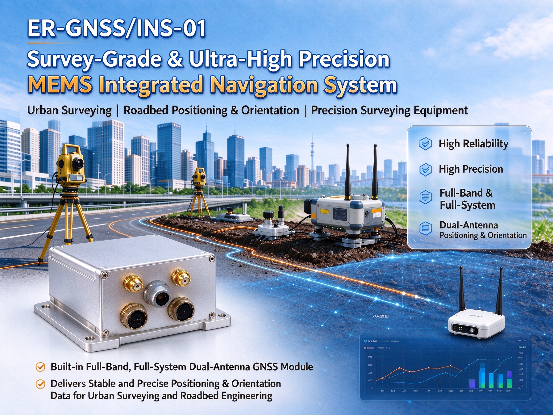
Understanding Dual-Antenna MEMS GNSS/INS Technology
What Is a MEMS GNSS/INS?
A MEMS GNSS/INS is an integrated navigation system that combines Global Navigation Satellite System (GNSS) positioning with an Inertial Navigation System (INS).
The GNSS receiver obtains satellite-based positioning, velocity, and timing information. The inertial navigation unit uses MEMS gyroscopes and accelerometers to measure angular velocity and linear acceleration.
These two technologies have complementary characteristics.
GNSS provides an external reference for correcting accumulated inertial navigation errors. Inertial sensors provide high-rate motion measurements and can continue supplying navigation information during temporary satellite signal interruptions.
A navigation fusion algorithm processes the information from both systems and generates Position, Velocity, and Attitude (PVA) data.
Depending on the system architecture, the integration may use different GNSS/INS coupling methods. The selected approach, sensor quality, calibration, and processing algorithm all influence final navigation performance.
How GNSS and MEMS Inertial Sensors Work Together
A typical MEMS GNSS/INS contains several major components:
- GNSS receiver: Receives satellite signals and calculates positioning and velocity information.
- MEMS gyroscopes: Measure angular velocity around three axes and help determine changes in platform orientation.
- MEMS accelerometers: Measure acceleration along three axes and provide motion information for inertial navigation calculations.
- Navigation processor: Processes sensor measurements and performs coordinate transformations and navigation calculations.
- Fusion algorithm: Combines GNSS and inertial information to estimate navigation states and compensate for sensor errors.
During normal operation, GNSS measurements help constrain inertial navigation errors. At the same time, the IMU provides continuous motion information between GNSS updates.
When satellite observations become unavailable, the INS can temporarily continue calculating the platform's movement from inertial measurements.
The duration and accuracy of this autonomous navigation period depend on the quality of the inertial sensors, initial navigation conditions, vehicle dynamics, calibration, and system algorithm.
Why Dual-Antenna GNSS Matters for Navigation Accuracy
A dual-antenna GNSS configuration uses two antennas installed at a known distance and orientation relative to the navigation platform.
By processing satellite carrier-phase observations from both antennas, the receiver can determine the direction of the baseline between them. This provides a GNSS-derived heading reference that does not depend solely on the platform moving forward.
This characteristic is particularly valuable when a vehicle is stationary, moving slowly, or operating in conditions where motion-based heading estimation is unreliable.
The antenna baseline is an important factor. A properly installed and sufficiently long baseline generally provides better heading observability, subject to satellite geometry, signal quality, antenna installation, and receiver performance.
For applications requiring reliable heading information before or during movement, dual-antenna GNSS can offer a significant advantage over conventional single-antenna configurations.
Single-Antenna vs. Dual-Antenna MEMS GNSS/INS
Choosing between single-antenna and dual-antenna navigation depends on the platform's operating conditions and heading requirements.
Both configurations can provide satellite positioning and velocity information, but their heading determination methods are different.
How Single-Antenna GNSS/INS Determines Heading
A single-antenna GNSS receiver generally estimates direction of travel from the platform's movement.
This method is often referred to as course over ground. When a vehicle moves steadily, its direction of travel can provide useful heading information.
However, direction of travel is not always identical to the physical orientation of the platform.
For example, a vehicle operating at very low speed may have insufficient movement to calculate a stable course. A vehicle moving sideways, reversing, or experiencing significant sideslip may also have a difference between its travel direction and body heading.
In these situations, the INS and other available sensors must contribute to orientation estimation.
Single-antenna systems are often suitable when installation simplicity, cost, and positioning performance are the primary considerations.
How Dual-Antenna GNSS/INS Determines Heading
A dual-antenna system determines heading from the relative position of two GNSS antennas.
Because the distance and orientation between the antennas are known, the GNSS receiver can calculate the baseline direction using satellite observations.
Unlike motion-based heading estimation, this method can provide a heading reference even when the platform is stationary, provided that both antennas have sufficient satellite visibility and the receiver has completed the required initialization.
A longer antenna baseline can improve heading determination under suitable conditions. However, actual accuracy also depends on antenna quality, mounting alignment, satellite geometry, multipath interference, and receiver specifications.
Key Differences Between Single and Dual Antennas
| Comparison | Single-Antenna GNSS/INS | Dual-Antenna GNSS/INS |
|---|---|---|
| Antenna quantity | One | Two |
| Positioning | Supported | Supported |
| Velocity measurement | Supported | Supported |
| Heading reference | Primarily movement-based GNSS course and INS | GNSS antenna baseline and INS |
| Static heading | Depends on inertial alignment and other available references | GNSS-based heading is possible with valid observations |
| Low-speed heading | May be challenging | More suitable for applications requiring a static or low-speed heading reference |
| Installation | Generally simpler | Requires two antennas and a defined baseline |
| Typical application | Cost-sensitive navigation platforms | Platforms requiring more reliable heading determination |
How to Choose the Right Antenna Configuration
A single-antenna system may be appropriate when the platform normally moves at a sufficient speed and does not require a reliable GNSS-derived heading while stationary.
A dual-antenna system is worth considering when the application requires:
- Heading determination before the platform begins moving.
- More reliable heading information at low speed.
- Accurate orientation for autonomous steering.
- Navigation and positioning with a clearly defined antenna baseline.
- Integrated position, velocity, and attitude information.
For platforms where heading accuracy directly affects control decisions, the antenna configuration should be evaluated at the beginning of system design rather than treated as a secondary installation detail.
Key Performance Parameters When Selecting a MEMS GNSS/INS
A navigation system should be evaluated according to the requirements of its actual application. Several important parameters determine whether a MEMS GNSS/INS is suitable for a particular platform.
Roll and Pitch Accuracy
Roll and pitch describe the platform's orientation relative to the horizontal reference.
These parameters are important for UAV flight control, vehicle stability monitoring, surveying equipment, and attitude measurement systems.
For example, a UAV requires accurate roll and pitch information to maintain flight stability and execute precise maneuvers.
When comparing specifications, check whether the manufacturer provides real-time accuracy, static accuracy, or post-processing accuracy. These values should not be treated as interchangeable.
Heading Accuracy and Antenna Baseline
Heading determines the direction in which the platform is oriented.
It is particularly important for unmanned vehicles, navigation systems, surveying equipment, and platforms that need to follow a planned route.
For a dual-antenna system, heading accuracy should always be evaluated together with the antenna baseline.
A heading specification obtained with a 2-meter baseline should not automatically be assumed to apply when the antennas are installed only 0.5 meters apart.
Before purchasing a system, confirm the baseline length required to achieve the specified heading performance.
GNSS RTK Positioning Accuracy
Real-Time Kinematic (RTK) positioning uses carrier-phase measurements and correction information to improve GNSS positioning accuracy.
RTK is particularly useful for applications requiring centimeter-level positioning, including surveying, precision mapping, machine guidance, and certain autonomous platforms.
However, RTK performance depends on several factors:
- Availability and quality of correction data.
- GNSS satellite visibility and geometry.
- Antenna installation and signal reception.
- Baseline distance and correction service conditions.
- Environmental interference and multipath effects.
When comparing products, distinguish between RTK positioning accuracy under normal GNSS reception and positioning performance during a GNSS outage.
Gyroscope Bias Instability and Angular Random Walk
A gyroscope measures angular velocity. Its error characteristics directly influence the accuracy of inertial attitude and heading calculations.
Two parameters worth examining are bias instability and angular random walk (ARW).
Bias instability describes changes in the gyroscope's bias over time. Angular random walk represents the accumulation of angle error associated with gyroscope noise.
Generally, lower values indicate better sensor performance, but the final navigation accuracy also depends on calibration, temperature compensation, alignment, and the fusion algorithm.
Accelerometer Bias Stability
MEMS accelerometers measure linear acceleration.
Their bias errors can contribute to velocity and position errors when acceleration measurements are integrated over time.
This is why accelerometer bias stability is especially important for GNSS/INS systems expected to maintain navigation during temporary satellite interruptions.
When comparing accelerometers, make sure the figures use comparable measurement definitions and test conditions. Values based on different Allan variance intervals or statistical methods should not be compared directly.
Navigation Update Rate and Environmental Adaptability
The navigation output rate determines how frequently the host platform receives updated navigation information.
A UAV flight-control system may have different data-rate requirements from a road vehicle, surveying platform, or marine navigation system.
Other factors include operating temperature, vibration resistance, power consumption, mechanical installation, and communication interfaces.
A suitable navigation system should meet both the sensor performance requirements and the integration requirements of the complete platform.
How Does MEMS GNSS/INS Maintain Navigation During GNSS Outages?
GNSS signal interruptions can occur in tunnels, urban canyons, areas with heavy satellite obstruction, or environments affected by radio-frequency interference.
When GNSS updates are unavailable, a standalone GNSS receiver cannot continue providing normal satellite-based positioning.
An integrated INS can temporarily maintain navigation calculations using its gyroscopes and accelerometers.
The Role of MEMS Gyroscopes and Accelerometers
During normal operation, GNSS measurements help correct the accumulated errors of the inertial navigation solution.
When satellite signals are lost, the system uses angular velocity and acceleration measurements to estimate changes in orientation, velocity, and position.
This process is commonly known as inertial navigation or dead reckoning.
However, inertial navigation errors accumulate over time. Gyroscope bias affects attitude estimation, while accelerometer errors can contribute to increasing velocity and position errors.
Consequently, short-term GNSS outage performance is an important parameter when selecting a MEMS GNSS/INS.
Understanding 30-Second and 60-Second GNSS Outage Performance
A system that maintains stable attitude during a short GNSS interruption may not maintain the same positioning accuracy over a longer interruption.
For this reason, manufacturers should provide separate performance figures for different outage durations whenever possible.
The ER-GNSS/MINS-03 specification lists the following performance under its 30-second and 60-second RTK outage conditions:
| Parameter | 30-Second RTK Outage | 60-Second RTK Outage |
|---|---|---|
| Roll & Pitch | 0.01° | 0.02° |
| Heading | 0.02° | 0.03° |
| Horizontal Position (X/Y) | 0.5 m | 1.5 m |
| Altitude (Z) | 0.25 m | 1.0 m |
These figures illustrate an important characteristic of integrated navigation: attitude and heading can remain relatively stable during a short satellite interruption, while position errors increase as the outage continues.
The values should be understood as specified test results, not as universal guarantees for every vehicle or operating environment.
Actual performance can be influenced by initial alignment, sensor temperature, vehicle movement, GNSS conditions before signal loss, and the duration of the interruption.
It is also important to distinguish a complete GNSS signal outage from a loss of RTK correction data. Losing correction information does not necessarily mean that all satellite observations have disappeared. These two conditions can produce different navigation results.
Why GNSS Outage Performance Matters
For autonomous vehicles, UAVs, and other mobile platforms, a temporary positioning interruption can affect navigation continuity and control decisions.
An integrated GNSS/INS can help bridge short periods without satellite updates, allowing the host system to continue receiving inertial navigation information.
Nevertheless, an INS should not be viewed as a permanent replacement for GNSS. For applications involving extended signal denial, system designers may need additional navigation references, such as wheel odometry, visual positioning, Doppler velocity logs, or other external sensors.
Applications of Dual-Antenna MEMS GNSS/INS
Dual-antenna MEMS GNSS/INS technology can support different types of mobile platforms. Its suitability depends on the required position, velocity, heading, attitude, and GNSS outage performance.
UAV Navigation and Flight Data Recording
UAVs need accurate attitude and heading information to maintain stable flight and follow planned routes.
GNSS provides absolute positioning, while the IMU supplies motion measurements at a high rate.
A dual-antenna configuration can provide an additional heading reference, which may be useful for larger UAVs, specialized aerial platforms, and systems requiring reliable orientation information during startup or low-speed operation.
Integrated navigation information can also support flight data recording, aerial surveying, and navigation system development.
Autonomous Ground Vehicles and Intelligent Unmanned Vehicles
Autonomous ground vehicles rely on accurate position and heading information to determine their location and execute navigation decisions.
Urban environments, elevated roads, buildings, and other obstructions can affect satellite reception.
A GNSS/INS helps combine satellite positioning with inertial motion measurements, providing a more continuous navigation solution during temporary signal interruptions.
Dual-antenna heading can also support autonomous steering and vehicle orientation estimation, especially when the platform operates at low speed or temporarily stops.
Marine Surveying and Waterway Detection
Marine surveying platforms require reliable positioning, heading, and attitude information for route tracking, hydrographic measurements, and waterway detection.
Dual-antenna GNSS/INS can provide a GNSS-derived heading reference and combine it with inertial measurements to support navigation and surveying tasks.
For marine applications, designers should also consider installation geometry, antenna visibility, vessel vibration, and the effects of platform motion.
ROV and Autonomous Underwater Vehicle Navigation
Remotely operated vehicles (ROVs) and autonomous underwater vehicles (AUVs) present a different navigation challenge because GNSS signals cannot normally be received underwater.
An INS can provide short-term navigation through inertial measurements, but accumulated errors must be controlled through appropriate external aiding systems.
Depending on the platform, these may include Doppler velocity logs (DVL), acoustic positioning systems, depth sensors, or surface GNSS updates.
A MEMS GNSS/INS can therefore be part of an integrated underwater navigation architecture, but the complete system must be designed around the actual underwater operating conditions.
Roadbed Positioning and Orientation
Road construction and infrastructure equipment may require accurate position and orientation information for alignment, positioning, and operational monitoring.
A GNSS/INS can combine satellite positioning with inertial measurements to provide navigation data for mobile machinery and surveying platforms.
For these applications, the system should be selected according to the required positioning accuracy, working environment, vibration conditions, output rate, and equipment integration requirements.
ER-GNSS/MINS-03: A Cost-Effective Dual-Antenna MEMS Integrated Navigation System
For applications requiring integrated satellite positioning, inertial navigation, and dual-antenna heading determination, ER-GNSS/MINS-03 from Ericco is a cost-effective MEMS integrated navigation solution.
It combines tactical-grade MEMS inertial sensors, a full-band and full-constellation dual-antenna GNSS module, and an integrated navigation fusion algorithm.
The system is designed to provide position, velocity, and attitude information for land, aviation, and other navigation applications.
Tactical-Grade MEMS Gyroscope and Accelerometer
ER-GNSS/MINS-03 uses MEMS gyroscopes and accelerometers designed to provide reliable inertial measurements.
Its published sensor specifications include:
| Sensor Parameter | ER-GNSS/MINS-03 Specification |
|---|---|
| Gyroscope Bias Instability | <0.3°/h |
| Gyroscope Angular Random Walk | <0.125°/√h |
| Gyroscope Measurement Range | ±400°/s |
| Gyroscope Bandwidth (-3 dB) | 250 Hz |
| Accelerometer Bias Stability (Allen) | <10 μg |
| Accelerometer Bias Stability (1σ, 10 s) | <50 μg |
| Accelerometer Measurement Range | ±10 g |
| Accelerometer Bandwidth | 100 Hz |
These sensor characteristics help the integrated navigation algorithm estimate platform motion and maintain navigation calculations during temporary GNSS interruptions.
Built-In Dual-Antenna GNSS Positioning and Heading
ER-GNSS/MINS-03 integrates a dual-antenna, multi-constellation GNSS module.
It supports BDS, GPS, GLONASS, Galileo, and QZSS satellite navigation systems.
The GNSS module supports single-antenna positioning and velocity measurement, together with dual-antenna heading determination.
With a 2-meter antenna baseline, the system provides a specified heading accuracy of 0.05°. The published post-processing heading accuracy is 0.01°.
For system integrators, the antenna baseline and installation alignment should be considered during platform design to achieve the expected heading performance.
RTK Positioning Performance
ER-GNSS/MINS-03 supports RTK positioning for applications requiring high-accuracy satellite-based positioning.
Its published positioning specifications include:
| Positioning Mode | Horizontal Accuracy | Vertical Accuracy |
|---|---|---|
| Single-Point Positioning | 1.5 m | 2.5 m |
| DGPS | 0.4 m + 1 ppm | 0.8 m + 1 ppm |
| RTK | 0.8 cm + 1 ppm | 1.5 cm + 1 ppm |
These values describe positioning performance under the corresponding GNSS operating conditions. RTK results depend on satellite observations, correction data, antenna installation, and the surrounding environment.
When GNSS signals are interrupted, the system switches to inertial navigation to maintain short-term navigation output, with the outage figures described in the previous section.
Multiple Communication Interfaces and Environmental Adaptability
Different autonomous platforms use different onboard computers, controllers, and data acquisition systems.
ER-GNSS/MINS-03 supports RS422, RS232, and CAN communication interfaces, providing integration options for different host platforms.
The system also uses a precision aluminum alloy housing and supports temperature compensation for the gyroscope and accelerometer across its specified operating temperature range.
Its published operating temperature is -40°C to +80°C.
These characteristics make it suitable for evaluation in different land-based and aviation navigation systems.
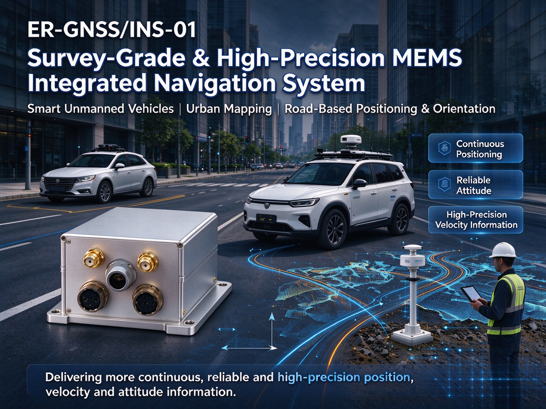
Typical Applications
According to its product specifications, ER-GNSS/MINS-03 is suitable for applications including:
- UAV navigation and flight recorders.
- Intelligent unmanned vehicles.
- Roadbed positioning and orientation.
- Waterway detection.
- ROV and AUV navigation system integration.
For underwater applications, additional external aiding and system-level integration may be required because GNSS signals are unavailable underwater.
Product Reference: ER-GNSS/MINS-03 Cost-Effective MEMS Integrated Navigation System
How to Select the Right MEMS Integrated Navigation System for Your Project
Selecting a navigation system requires matching its technical specifications with the operating requirements of the complete platform.
Before purchasing a dual-antenna MEMS GNSS/INS, engineering teams and procurement specialists should evaluate the following factors.
Define Your Required Positioning and Attitude Accuracy
Start by identifying the accuracy requirements for position, velocity, roll, pitch, and heading.
A surveying platform may prioritize RTK positioning, while an autonomous vehicle may place greater emphasis on heading stability and continuous navigation.
Do not select a product based on a single accuracy figure. Evaluate the complete navigation solution.
Determine Whether Single or Dual Antennas Are Needed
Consider whether the platform needs a reliable heading reference while stationary or moving slowly.
If it relies on GNSS course over ground and normally moves at a sufficient speed, a single-antenna configuration may be adequate.
If heading must be determined without relying solely on forward movement, a dual-antenna system may be more suitable.
Evaluate RTK and GNSS Outage Requirements
Identify whether the application needs centimeter-level positioning under normal RTK conditions.
Then evaluate how the system performs when satellite observations or correction data become unavailable.
Specify the expected outage duration and the maximum acceptable position, attitude, and heading errors.
Consider Platform Size, Weight, and Power Requirements
Mechanical dimensions, weight, supply voltage, and power consumption affect system integration.
These parameters are especially important for UAVs and other platforms with strict payload and energy limitations.
Request the complete mechanical and electrical specifications before finalizing the product selection.
Check Communication Interfaces and System Compatibility
Confirm that the navigation system can communicate with the host controller or onboard computer.
Common considerations include RS422, RS232, CAN, data protocols, output frequency, time synchronization, and coordinate system configuration.
The available interface name alone does not confirm that the device supports every communication protocol required by a particular platform.
Evaluate Manufacturer Technical Support and Customization
For OEM and project-based procurement, technical support is also an important selection criterion.
Before ordering, confirm antenna installation requirements, calibration procedures, available communication protocols, environmental specifications, and integration documentation.
A supplier that can provide clear technical documentation and engineering support can help reduce integration risks during system development.
FAQ
Q1: What Is the Difference Between MEMS INS and GNSS/INS?
A MEMS INS calculates navigation information using inertial sensors, including gyroscopes and accelerometers.
A GNSS/INS combines inertial navigation with satellite positioning. GNSS provides external position and velocity references, helping control the accumulation of inertial navigation errors.
Q2: How Does a Dual-Antenna GNSS/INS Determine Heading?
A dual-antenna GNSS/INS determines heading by measuring the direction of the baseline between two GNSS antennas.
The receiver processes satellite observations from both antennas to calculate the baseline orientation. This allows the system to obtain a GNSS-derived heading reference without relying exclusively on the platform moving forward.
Q3: Can a MEMS GNSS/INS Work When GNSS Signals Are Lost?
Yes. An integrated GNSS/INS can temporarily continue calculating navigation information using its MEMS gyroscopes and accelerometers.
However, inertial navigation errors increase over time. The available outage duration and navigation accuracy depend on sensor performance, initialization, vehicle dynamics, and the system algorithm.
Q4: How Accurate Is a Dual-Antenna MEMS GNSS/INS?
Accuracy varies by product, antenna baseline, satellite conditions, and operating mode.
For example, ER-GNSS/MINS-03 specifies 0.05° heading accuracy with a 2-meter dual-antenna baseline, 0.02° roll and pitch accuracy, and RTK horizontal positioning accuracy of 0.8 cm + 1 ppm under specified operating conditions.
Actual application performance should be evaluated against the manufacturer's test conditions.
Q5: Does ER-GNSS/MINS-03 Support RTK Positioning?
Yes. ER-GNSS/MINS-03 supports RTK positioning, with published accuracy of 0.8 cm + 1 ppm horizontally and 1.5 cm + 1 ppm vertically.
RTK performance requires suitable GNSS observations and valid correction information.
Q6: What Is the GNSS Outage Performance of ER-GNSS/MINS-03?
Its product specifications provide separate 30-second and 60-second RTK outage results.
At 30 seconds, the specified roll and pitch accuracy is 0.01°, heading is 0.02°, and horizontal position error is 0.5 m.
At 60 seconds, roll and pitch accuracy is 0.02°, heading is 0.03°, and horizontal position error is 1.5 m.
These are specified test results rather than universal guarantees for every application.
Q7: What Communication Interfaces Does ER-GNSS/MINS-03 Support?
ER-GNSS/MINS-03 supports RS422, RS232, and CAN communication interfaces.
For specific integration projects, users should confirm the communication protocol, pin definition, data format, output frequency, and synchronization requirements.
Q8: What Applications Are Suitable for ER-GNSS/MINS-03?
Typical applications listed by Ericco include UAV navigation, flight recorders, intelligent unmanned vehicles, roadbed positioning and orientation, waterway detection, and ROV/AUV navigation integration.
For underwater platforms, additional external positioning or velocity-aiding equipment may be needed.
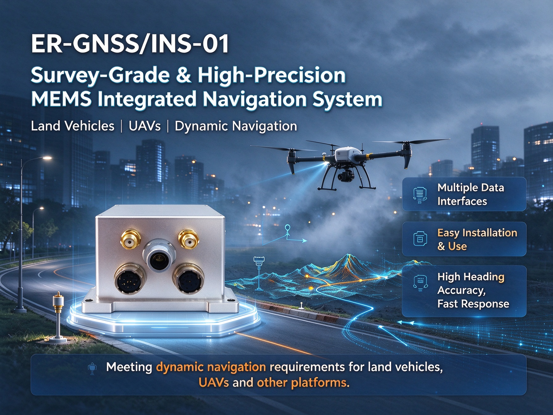
Conclusion: Choosing a Reliable Dual-Antenna MEMS GNSS/INS
A dual-antenna MEMS GNSS/INS combines satellite positioning and inertial measurement technology to provide integrated position, velocity, and attitude information.
Its key advantages include GNSS-derived heading, RTK positioning capability, and short-term navigation continuity during satellite signal interruptions.
When selecting a system, engineering teams should evaluate more than nominal positioning accuracy. Antenna baseline, gyroscope and accelerometer performance, GNSS outage behavior, communication interfaces, environmental conditions, and platform integration requirements all affect the final navigation solution.
For UAVs, intelligent unmanned vehicles, surveying platforms, and other applications requiring integrated navigation, ER-GNSS/MINS-03 offers a cost-effective combination of tactical-grade MEMS inertial sensors, dual-antenna GNSS, RTK positioning, and multiple communication interfaces.
To evaluate whether ER-GNSS/MINS-03 meets your project requirements, contact Ericco with your required positioning accuracy, heading accuracy, antenna baseline, operating environment, and communication interface.
Explore the product: ER-GNSS/MINS-03 Cost-Effective MEMS Integrated Navigation System
Contact Ericco for Technical Support and Product Inquiry:
Email: info@ericcointernational.com
Website: https://www.ericcointernational.com/