

Downhole MEMS Gyro Modules: Working Principles, Selection Criteria, and Integration
Accurate wellbore trajectory measurement is essential for modern oil and gas drilling, mining exploration, and underground directional drilling. As drilling operations extend into more complex geological formations and magnetically disturbed environments, conventional magnetic directional sensors may encounter limitations in azimuth measurement accuracy and reliability.
A Downhole MEMS Gyro Module provides an alternative approach by using inertial measurement technology to determine azimuth, inclination, and tool face angles without relying on the Earth's magnetic field.
For equipment manufacturers and downhole measurement system integrators, selecting the right MEMS gyroscopic directional module involves more than comparing accuracy specifications. Factors such as sensor architecture, alignment time, operating temperature, mechanical dimensions, communication interfaces, and system compatibility must also be considered.
This guide explains how downhole MEMS gyro modules work, what technical specifications matter during product selection, and how to integrate these modules into gyro tools and directional measurement systems. It also introduces Ericco's ER-Gyro-15 as an example of a compact MEMS directional module designed for demanding downhole applications.
What Is a Downhole MEMS Gyro Module?
A downhole MEMS gyro module is an inertial sensing component designed to measure the orientation and directional information of underground drilling or surveying equipment.
MEMS stands for Micro-Electro-Mechanical Systems. MEMS gyroscopes detect angular motion, while MEMS accelerometers measure specific force, including the gravity-related components used to determine inclination and attitude.
By combining these sensors with an inertial measurement and attitude calculation algorithm, a MEMS gyro directional module can provide several important measurement outputs:
- Azimuth: The horizontal direction of the borehole or drilling instrument relative to a reference direction.
- Inclination: The angle between the borehole axis and the vertical direction.
- Gravity Tool Face (GTF): The rotational orientation of the tool relative to the gravity reference.
- Gyro Tool Face (GTF): The tool's rotational orientation determined using gyroscopic directional information.
These measurements are important for determining wellbore trajectories, controlling drilling direction, and evaluating underground equipment orientation.
Unlike magnetic directional sensors, a gyroscopic directional module can determine directional information without using the Earth's magnetic field as its heading reference. This makes it particularly useful in casing, tubing, steel structures, and other environments where magnetic interference may affect conventional measurement systems.
It is important to distinguish between a MEMS gyro module and a complete gyro survey tool. The module is an inertial measurement component, while a complete tool may also include a housing, power management, communication electronics, mechanical connections, data acquisition, and system-level software.
How Does a MEMS Gyro Directional Module Work?
A MEMS gyroscopic directional module typically combines three-axis gyroscopes, three-axis accelerometers, and an embedded processing system.
These components work together to calculate the orientation of the downhole instrument.
2.1 Three-Axis MEMS Gyroscope Technology
A three-axis MEMS gyroscope measures angular velocity around three mutually perpendicular axes: X, Y, and Z.
When the downhole tool rotates or changes orientation, the gyroscope detects the corresponding angular motion.
The measurement system processes these signals to determine changes in the instrument's orientation.
In gyro-based directional measurement, the Earth's rotation provides an inertial reference for determining north. This principle enables gyroscopic north finding without depending on geomagnetic field measurements.
For downhole applications, this is particularly valuable when the measurement instrument operates near steel casing, drill pipes, or other magnetically disturbing structures.
2.2 Three-Axis MEMS Accelerometer and Gravity Reference
A three-axis MEMS accelerometer measures specific force along the X, Y, and Z axes.
When the instrument is stationary or under suitable measurement conditions, the gravity-related components can be used to determine the orientation of the sensor relative to the vertical direction.
The accelerometer provides important information for calculating:
- Well inclination.
- Gravity tool face angle.
- Pitch and roll attitude.
- Orientation changes during measurement.
Combining gyroscope and accelerometer measurements provides a more complete description of the downhole tool's attitude.
2.3 Strapdown Inertial Measurement Technology
In a strapdown inertial measurement system, the inertial sensors are rigidly mounted to the instrument body rather than installed on a mechanically stabilized platform.
The gyroscopes and accelerometers continuously provide measurement data to the processing system.
The system uses sensor calibration, coordinate transformations, and attitude calculation algorithms to determine the instrument's orientation.
For downhole directional measurement, this architecture offers several engineering advantages:
- Compact mechanical structure.
- No requirement for a conventional gimbaled platform.
- Integration of multiple inertial sensors.
- Suitability for compact measurement probes.
- Support for attitude and directional data processing.
However, actual measurement performance depends on sensor quality, calibration, thermal compensation, alignment procedures, and the algorithms used by the complete system.
2.4 True North Determination Based on Earth's Rotation
One of the most important capabilities of a gyroscopic directional module is its ability to determine north independently of magnetic field measurements.
The Earth's rotation provides a natural inertial reference. A sufficiently accurate gyroscope can detect the relevant rotational component and use it to calculate geographic north.
This is commonly referred to as gyrocompassing or gyroscopic north finding.
The measurement process generally involves:
- Initializing the inertial measurement system.
- Acquiring gyroscope and accelerometer data.
- Establishing the instrument's attitude relative to gravity.
- Measuring the Earth's rotational component.
- Calculating the azimuth relative to geographic north.
The accuracy of this process depends on gyroscope performance, geographic latitude, alignment time, temperature conditions, and the quality of the measurement environment.
2.5 Attitude Calculation and Directional Data Output
After acquiring inertial sensor data, the processing system calculates the instrument's orientation and directional parameters.
Depending on the system architecture, the module can provide azimuth, inclination, gyro tool face, and gravity tool face information.
These outputs can then be transferred to the host instrument through a communication interface for further processing, display, recording, or wellbore trajectory calculation.
Why Are MEMS Gyro Modules Used in Downhole Measurement Systems?
Downhole measurement environments present several challenges that are not always encountered in conventional surface navigation applications.
A directional module must operate within restricted mechanical spaces and withstand environmental conditions while maintaining reliable measurement performance.
3.1 Directional Measurement in Magnetic Interference Environments
Magnetic interference is a major consideration in underground directional measurement.
Steel casing, drill pipes, metal structures, and nearby equipment can distort the local magnetic field. This may affect the performance of magnetometer-based directional measurement systems.
A gyroscopic directional module uses inertial sensing rather than magnetic field direction as its north reference.
This makes gyro-based measurement especially suitable for:
- Cased-hole surveying.
- Directional measurement near steel structures.
- Underground mining operations.
- Magnetically disturbed drilling environments.
- Wellbore trajectory surveys where magnetic reference reliability is limited.
It is important to understand that magnetic independence does not eliminate every source of measurement error. Sensor drift, vibration, thermal effects, alignment errors, and mechanical installation conditions must still be controlled.
3.2 Directional Measurement at Small Well Inclinations
Small well inclination angles can create challenges for directional measurement.
When the tool is close to vertical, gravity provides less horizontal directional information. As a result, azimuth determination becomes more dependent on gyroscope performance and the quality of the alignment process.
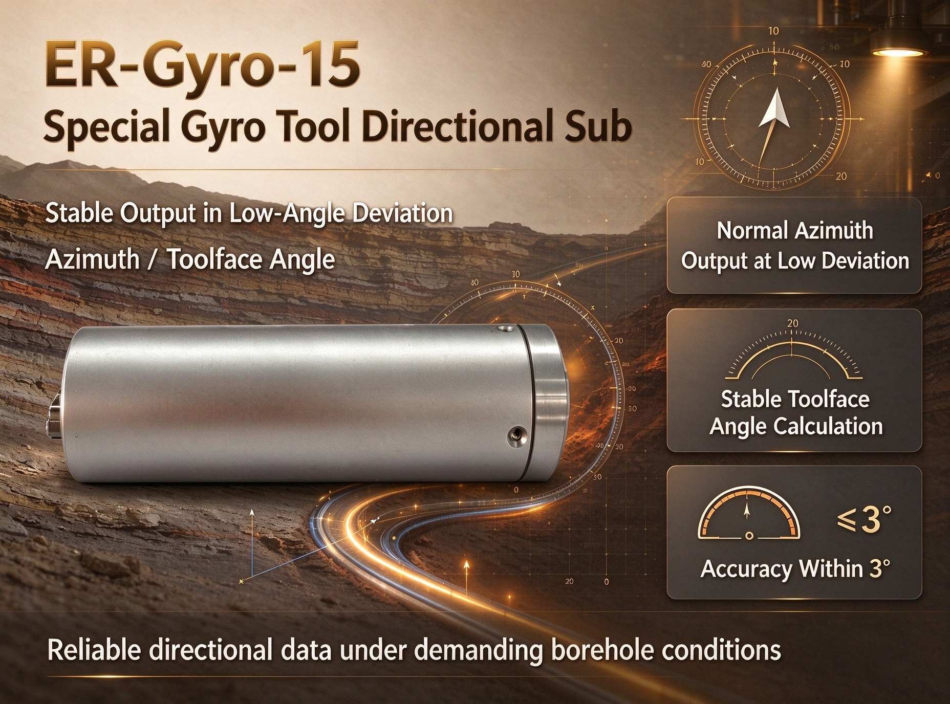
A high-performance MEMS gyro module designed for small-inclination applications can help address this challenge.
When evaluating a product, engineers should examine the specified azimuth accuracy under different inclination conditions rather than relying on a single headline accuracy value.
3.3 Compact Design for Narrow Downhole Probes
Space is a significant design constraint in downhole instruments.
Traditional directional equipment may require relatively large mechanical structures, making integration difficult in narrow probes or compact measurement assemblies.
Miniaturized MEMS gyro modules offer more flexibility in mechanical design.
Their compact dimensions can help equipment manufacturers:
- Reduce the space occupied by the sensing assembly.
- Simplify probe integration.
- Optimize the internal layout of downhole instruments.
- Reserve space for additional electronic components.
- Develop more compact directional measurement systems.
Mechanical compatibility must still be evaluated according to the actual housing, connector, mounting structure, and installation tolerances.
3.4 Shock and Vibration Resistance
Downhole drilling operations can involve continuous vibration, mechanical shock, and changing dynamic conditions.
These factors may affect sensor readings and measurement stability.
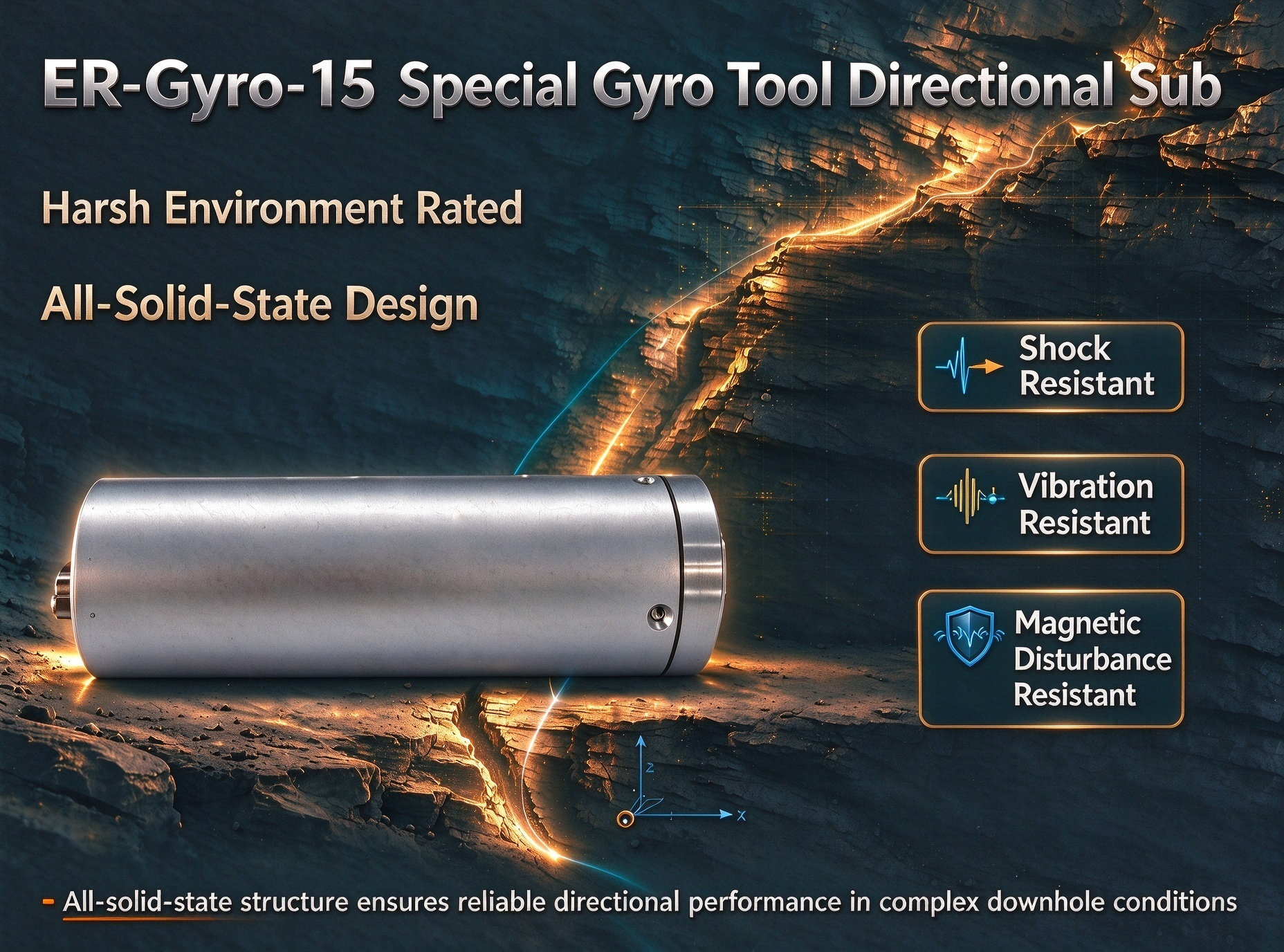
An all-solid-state MEMS architecture eliminates the need for conventional moving gimbal mechanisms, which can simplify the mechanical structure.
However, the presence of a solid-state design alone does not establish a specific vibration or shock rating.
For equipment integration, manufacturers should review actual shock and vibration test reports, including acceleration levels, frequency ranges, test duration, and measurement performance during or after testing.
3.5 High-Temperature Downhole Applications
Temperature is another important factor in downhole measurement.
Electronic components and MEMS sensors may experience performance changes as operating temperatures vary.
Temperature calibration and compensation help reduce temperature-related measurement errors.
When selecting a module for high-temperature applications, engineers should verify:
- Continuous operating temperature.
- Maximum rated temperature.
- Storage temperature.
- Temperature compensation range.
- Accuracy across the specified operating range.
- Thermal cycling test results.
The temperature rating of an individual module should also be distinguished from that of the complete downhole instrument.
Key Parameters When Selecting a Downhole MEMS Gyro Module
For OEM manufacturers and system integrators, a technical specification sheet is one of the most important tools during product selection.
The following parameters should be evaluated together rather than independently.
4.1 Azimuth Accuracy
Azimuth accuracy describes how closely the measured direction corresponds to the reference direction.
It is one of the primary performance indicators for downhole gyro surveying applications.
When comparing products, check:
- Whether accuracy is expressed as 1σ or another statistical measure.
- Whether accuracy depends on geographic latitude.
- Whether the specification is valid at small well inclinations.
- Whether the value represents static alignment or dynamic operation.
- Whether the test conditions are clearly defined.
A product with a nominal 0.5° specification may perform differently under different operating and alignment conditions. Therefore, accuracy figures should always be interpreted together with their test methodology.
4.2 Well Inclination Accuracy
Inclination accuracy determines how precisely the instrument measures the angle between the borehole axis and the vertical direction.
This parameter affects wellbore trajectory calculations and directional control.
For many surveying applications, even relatively small inclination errors can influence the calculated position of the wellbore over a long measured depth.
A suitable module should provide clearly specified inclination accuracy and measurement range.
4.3 Gyro Tool Face and Gravity Tool Face Accuracy
Tool face information describes the rotational orientation of the drilling instrument.
Gravity tool face is referenced to gravity, while gyro tool face is determined using gyroscopic directional information.
Both measurements may be relevant depending on the drilling system and operating conditions.
When evaluating a module, verify:
- Tool face measurement range.
- Accuracy definition.
- Coordinate reference.
- Relationship between the sensor axes and tool body.
- Performance under the intended measurement conditions.
4.4 Alignment Time and Accuracy Retention
Gyrocompassing requires an alignment process before reliable directional information can be obtained.
Alignment time describes how long the instrument needs to establish its reference orientation under specified conditions.
Some systems provide different alignment modes corresponding to different accuracy requirements.
Accuracy retention time describes the period over which specified measurement precision can be maintained under defined operating conditions.
These two parameters are important when designing measurement workflows, especially for equipment with limited downhole operating time.
4.5 Operating Temperature and Storage Temperature
Operating temperature defines the environmental range in which the module is designed to function.
Storage temperature defines the permissible temperature range when the module is not operating.
These specifications should not be treated as interchangeable.
For high-temperature applications, it is also necessary to understand whether the accuracy specification remains valid throughout the entire operating temperature range.
4.6 Module Dimensions and Weight
Mechanical dimensions directly influence whether a module can be integrated into an existing gyro tool.
Important considerations include:
- Outer diameter.
- Overall length.
- Weight.
- Connector position.
- Mounting orientation.
- Available installation clearance.
A smaller module can provide more design flexibility, but mechanical compatibility must be verified before procurement.
4.7 Power Supply and Communication Interface
Power requirements and communication interfaces determine how easily the module can connect to the host system.
Before selecting a module, engineers should confirm:
- Input voltage range.
- Power consumption.
- Communication interface type.
- Transmit and receive signal definitions.
- Connector configuration.
- Data format and communication protocol.
RS-422 is commonly used in industrial measurement systems because it supports differential serial communication.
However, interface compatibility should never be assumed from the interface name alone. The actual electrical specification and communication protocol must be checked.
4.8 Update Rate and Output Stability
The update rate indicates how frequently measurement data is refreshed or delivered, depending on the manufacturer's definition.
A higher update rate may be useful for applications requiring more frequent data acquisition.
Nevertheless, update rate is not the same as measurement accuracy.
System integrators should evaluate both the output frequency and the accuracy, stability, latency, and dynamic performance of the measurement data.
ER-Gyro-15: A MEMS Directional Module for Gyro Tools
For equipment manufacturers seeking a compact inertial measurement component, Ericco's ER-Gyro-15 is designed for integration into downhole gyro tools and directional measurement systems.
The module adopts strapdown inertial measurement technology based on three-axis navigation-grade MEMS gyroscopes and three-axis MEMS accelerometers.
It provides directional measurement information without relying on magnetic field references, making it suitable for applications where conventional magnetic sensors may encounter interference.
5.1 Product Overview
The ER-Gyro-15 is designed to provide three important types of directional information:
- Azimuth.
- Well inclination.
- Gyro and gravity tool face angles.
Its compact mechanical structure is intended for installation in restricted downhole probe spaces.
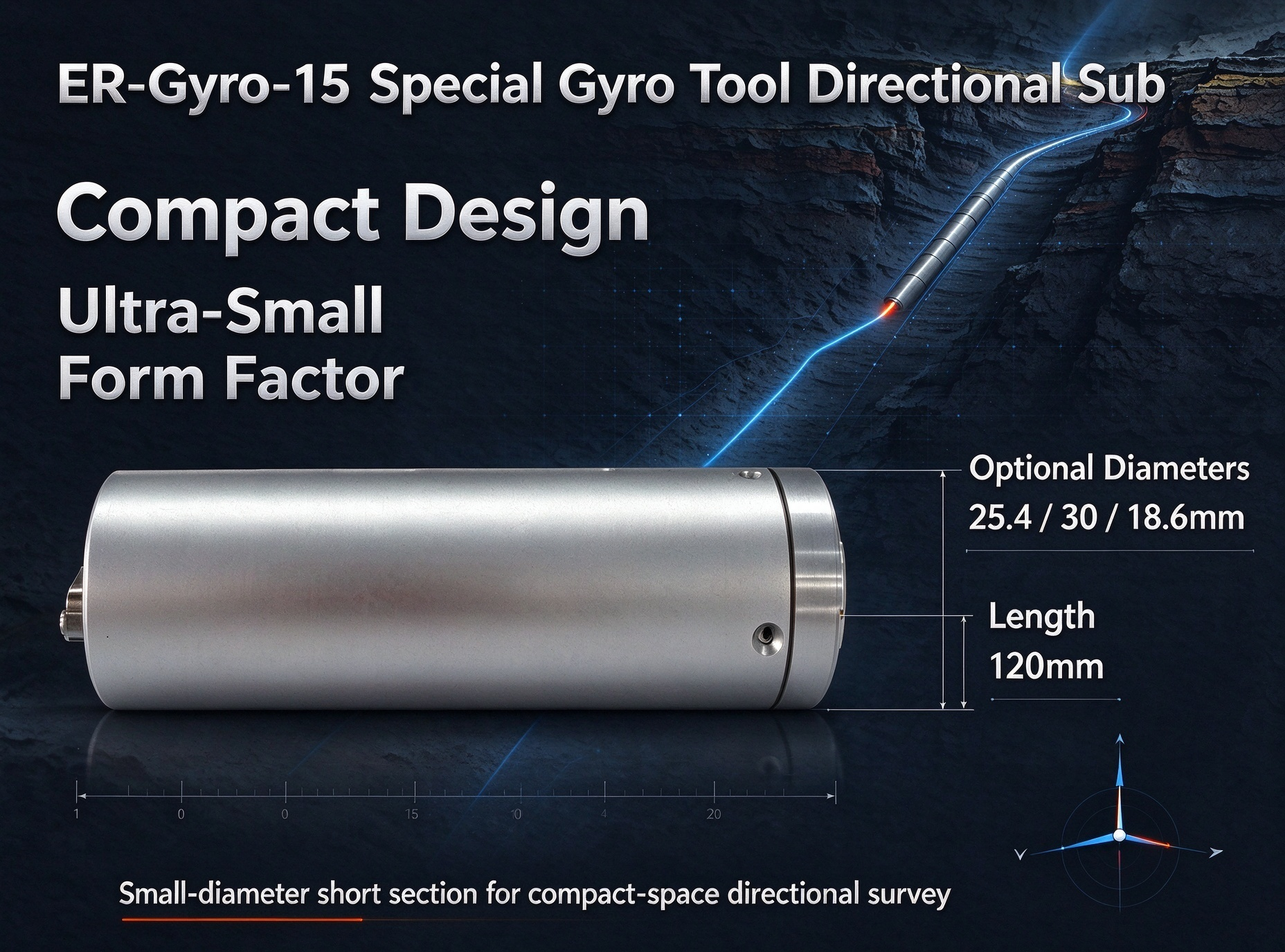
The product is available in three dimensional options, allowing equipment manufacturers to evaluate different mechanical configurations according to their instrument design.
5.2 ER-Gyro-15 Technical Specifications
The following table summarizes the published product specifications.
| Parameter | ER-Gyro-15 Specification |
|---|---|
| Models | ER-Gyro-15A / ER-Gyro-15B / ER-Gyro-15H |
| Azimuth accuracy | 1° or 0.5° (1σ, latitude-dependent specification) |
| Gyro tool face accuracy | 1°/secL (L represents latitude) |
| Well inclination alignment accuracy | 0.1° (1σ) |
| Alignment time | 90 s / 180 s |
| Azimuth precision retention time | 20 minutes |
| Attitude precision retention time | 20 minutes |
| Azimuth measurement range | 0°–360° |
| Gravity tool face range | -180°–180° |
| Gyro tool face range | 0°–360° |
| Well inclination range | 0°–180° |
| Update rate | 100 Hz |
| Operating temperature | 5°C to +85°C / 5°C to +125°C |
| Storage temperature | 0°C to +90°C / 0°C to +130°C |
| Power supply | 6–12 V |
| Power consumption | 2 W / 3 W |
| Communication interface | RS-422 |
| Dimensions | Φ30 × 120 mm / Φ25.4 × 120 mm / Φ18.6 × 120 mm |
| Weight | ≤150 g |
Note: Accuracy, alignment time, temperature, and power specifications depend on the selected model and operating configuration. Consult the official product datasheet for the exact model-to-parameter mapping before system integration.
5.3 Compact Mechanical Design and Installation Options
The ER-Gyro-15 offers three dimensional configurations:
- Option A: Φ30 mm × 120 mm.
- Option B: Φ25.4 mm × 120 mm.
- Option C: Φ18.6 mm × 120 mm.
These options provide flexibility for integration into different probe structures.
For OEM manufacturers, the smaller diameter options may be particularly useful when designing compact downhole measurement equipment.
Before installation, the mechanical design should account for sensor alignment, housing tolerances, connector access, mounting stability, and thermal expansion.
5.4 Electrical Interface and Data Communication
The ER-Gyro-15 uses an RS-422 communication interface and supports a 6–12 V power supply.
Its published connector is J30J-15ZKP.
The listed wiring definitions are:
| Pin | Definition |
|---|---|
| 1 | +6–12 V |
| 3 | GND |
| 6 | Tx+ |
| 7 | Tx- |
| 8 | Rx+ |
| 9 | Rx- |
| 10 | GND |
This interface provides a connection between the inertial module and the host equipment.
During system integration, engineers should confirm the communication protocol, baud rate, data packet format, grounding arrangement, and signal compatibility.
5.5 Which Applications Can Use ER-Gyro-15?
The ER-Gyro-15 is designed for directional measurement applications where compact dimensions and magnetic independence are important.
Potential application areas include:
Oil and Gas Drilling and Logging
The module can be integrated into gyro-based downhole measurement equipment used for wellbore directional surveying, including applications involving casing, tubing, and magnetically disturbed sections.
Mining and Underground Drilling
In underground environments containing steel infrastructure and heavy machinery, gyroscopic measurement can provide directional information without relying on magnetic field measurements.
Horizontal Directional Drilling (HDD)
Gyro-based directional measurement may be useful for pipeline installation and underground utility projects where magnetic interference can affect conventional directional references.
Geotechnical and Environmental Surveying
The module can also be considered for borehole trajectory measurement in geotechnical investigations and environmental monitoring well installations.
For application-specific integration, the final performance should be evaluated against the actual drilling conditions and host instrument requirements.
How to Integrate a MEMS Gyro Module into a Downhole Tool
Selecting a suitable module is only the first step. Successful integration requires coordinated mechanical, electrical, and software engineering.
6.1 Mechanical Installation and Probe Compatibility
The first step is confirming that the module fits the available installation space.
Engineers should check:
- Module diameter and overall length.
- Housing dimensions.
- Mounting structure.
- Connector clearance.
- Mechanical vibration isolation requirements.
- Sensor orientation relative to the tool body.
The module should be mounted securely to prevent unintended movement or misalignment during operation.
6.2 Coordinate Alignment and Sensor Calibration
Coordinate alignment is essential for accurate directional measurement.
The module's X, Y, and Z sensor axes must be correctly related to the coordinate system of the complete downhole instrument.
Incorrect installation orientation or coordinate transformation can introduce errors into calculated azimuth, inclination, and tool face values.
Calibration should account for sensor bias, scale factor, axis misalignment, and temperature-related effects where applicable.
6.3 Power Supply and Electrical Connections
The host system must provide a stable power supply within the module's specified voltage range.
Electrical integration should include:
- Correct power polarity.
- Appropriate grounding.
- Connector compatibility.
- Differential signal wiring.
- Electrical noise control.
- Protection against unintended power transients.
For ER-Gyro-15, the published supply range is 6–12 V.
6.4 RS-422 Communication and Data Acquisition
The host controller must be configured to communicate with the module through its RS-422 interface.
Before deployment, verify:
- Transmit and receive signal connections.
- Communication settings.
- Data packet structure.
- Measurement update frequency.
- Data validity and error handling.
- Communication reliability under operating conditions.
The communication protocol and data format should be obtained from the manufacturer rather than inferred from the physical interface.
6.5 System-Level Integration and Testing
After mechanical and electrical integration, the complete system should undergo functional testing.
The purpose is to verify that the module's outputs are correctly interpreted by the host system and that the complete instrument meets its application requirements.
Testing should include sensor initialization, alignment, directional output verification, communication stability, and repeatability.
How to Test the Performance of a Downhole MEMS Gyro Module
A module's published specifications are important, but actual system performance must be validated through appropriate testing.
The following procedures can help equipment manufacturers establish a more complete understanding of measurement performance.
7.1 Azimuth Accuracy Testing
Azimuth accuracy testing evaluates the difference between the module's measured direction and a reliable reference direction.
The test should document:
- Reference direction.
- Geographic latitude.
- Instrument orientation.
- Alignment procedure.
- Measurement duration.
- Statistical calculation method.
Because gyrocompassing performance may depend on latitude and inclination, the test conditions should be clearly defined.
7.2 Small-Inclination Measurement Testing
Small-inclination testing is particularly important for directional surveying applications involving nearly vertical boreholes.
The test should evaluate azimuth and tool face performance at different inclination angles.
Results should be compared with the manufacturer's specified accuracy under equivalent conditions.
7.3 Temperature Calibration and Compensation Testing
Temperature testing evaluates whether the module maintains acceptable performance across its specified operating temperature range.
A suitable test procedure may include:
- Temperature stabilization.
- Measurement at multiple temperature points.
- Repeated alignment tests.
- Comparison of measurement errors.
- Evaluation of thermal repeatability.
For high-temperature downhole applications, engineers should also assess the temperature capability of the complete instrument housing and electronic system.
7.4 Shock and Vibration Testing
Shock and vibration testing helps determine whether the module can withstand the mechanical conditions expected in the application.
Test reports should identify the vibration spectrum, acceleration level, shock pulse, test duration, and measurement behavior.
It is also useful to compare performance before and after testing to identify any permanent changes in sensor calibration.
7.5 Measurement Retention and Repeatability Testing
Repeated measurements can help evaluate consistency and stability.
Engineers should perform multiple alignment and measurement cycles under controlled conditions.
The results can be used to assess:
- Measurement repeatability.
- Alignment consistency.
- Azimuth precision retention.
- Attitude precision retention.
- Long-term stability under defined operating conditions.
7.6 Magnetic Interference Testing
Although a gyro-based module does not depend on magnetic north references, testing in magnetically disturbed environments can help demonstrate its application advantages.
Testing should compare the module's output under different magnetic conditions while controlling other variables.
It is important to distinguish magnetic independence from immunity to all environmental disturbances. Mechanical vibration, temperature variation, sensor drift, and installation errors can still affect inertial measurement performance.
Typical Applications of MEMS Gyro Directional Modules
MEMS gyro directional modules can be integrated into different types of underground surveying and drilling equipment.
8.1 Oil and Gas Well Logging
Well logging and trajectory surveying require accurate directional information to understand borehole orientation.
Gyro-based modules can be considered for measurement systems operating in casing, tubing, and other environments where magnetic reference measurements may be unreliable.
8.2 Gyro While Drilling (GWD) Systems
Gyro While Drilling systems use gyroscopic measurement technology to obtain directional information during drilling operations.
A MEMS gyro module can serve as an inertial sensing component within a larger GWD architecture.
However, continuous measurement during drilling requires the complete system to address dynamic vibration, rotation, signal processing, and measurement stability.
Module-level specifications should not automatically be interpreted as proof of complete GWD system performance.
8.3 Mining and Underground Directional Drilling
Underground mining operations frequently involve metal structures, heavy equipment, and restricted working spaces.
Gyroscopic directional measurement can provide an alternative to magnetic sensing in applications where magnetic interference is a concern.
The compact dimensions of MEMS modules also offer opportunities for integration into smaller surveying and drilling instruments.
8.4 Horizontal Directional Drilling
Horizontal directional drilling is widely used for underground pipeline and utility installation.
Directional information is necessary to maintain the planned drilling path and evaluate the installed route.
In magnetically disturbed areas, gyro-based directional measurement can provide a useful alternative reference for underground trajectory surveying.
8.5 Cased-Hole and Wellbore Trajectory Surveys
Steel casing and other metallic structures can complicate magnetic directional measurement.
Gyroscopic surveying provides a way to determine orientation without depending on the local magnetic field.
For cased-hole surveying, equipment manufacturers should evaluate module accuracy, alignment procedures, mechanical compatibility, and the complete survey workflow.
MEMS Gyro Module vs. Other Downhole Directional Technologies
Different directional measurement technologies serve different engineering requirements.
The correct choice depends on measurement accuracy, environmental conditions, mechanical constraints, system architecture, and project budget.
9.1 MEMS Gyro vs. Fluxgate Directional Sensor
A fluxgate directional sensor measures the Earth's magnetic field to determine directional information.
A MEMS gyro directional module uses inertial sensing and gyroscopic north finding.
The fundamental difference is the reference used for directional measurement.
| Comparison | MEMS Gyro Module | Fluxgate Directional Sensor |
|---|---|---|
| Measurement principle | Inertial sensing | Magnetic field sensing |
| North reference | Earth's rotation | Earth's magnetic field |
| Magnetic interference | Does not rely on magnetic north | Can be affected by magnetic disturbances |
| Typical application | Gyro-based directional measurement | Magnetic directional measurement |
| Integration considerations | Alignment, calibration, and inertial performance | Magnetic calibration and interference control |
Neither technology is universally suitable for every application. Equipment manufacturers should select the sensing approach according to actual environmental and performance requirements.
For a more detailed technical comparison, read Fluxgate vs. MEMS Gyro Directional Module: Complete Comparison.
9.2 MEMS Gyro vs. Conventional Mechanical Gyro
Conventional mechanical gyroscopes and MEMS gyroscopes use different sensing architectures.
Mechanical gyro systems may offer specific performance advantages in certain high-precision applications, but they can involve more complex mechanical structures.
MEMS gyro modules generally offer advantages in miniaturization, integration flexibility, and compact system design.
When comparing these technologies, consider:
- Accuracy requirements.
- Size and weight limitations.
- Environmental conditions.
- Maintenance requirements.
- Power consumption.
- Total system cost.
The appropriate technology depends on the intended measurement task rather than size or sensor category alone.
9.3 MEMS Gyro Module vs. Complete Gyro Survey Tool
A MEMS gyro module is not the same as a complete gyro survey tool.
The module provides inertial sensing and directional measurement outputs.
A complete survey tool incorporates the module into a larger system that may include:
- Mechanical housing.
- Power supply.
- Data acquisition electronics.
- Communication interfaces.
- Processing software.
- Data recording and display functions.
For OEM manufacturers, integrating a module into an existing instrument may offer greater flexibility than purchasing an entirely new measurement system.
FAQ
Q1. What Is a MEMS Gyro Directional Module?
A MEMS gyro directional module is an inertial sensing component that combines MEMS gyroscopes and accelerometers to measure azimuth, inclination, and tool face angles. It can be integrated into downhole gyro tools and directional surveying equipment.
Q2. How Does a Downhole Gyro Tool Determine True North?
A gyroscopic north-finding system uses the Earth's rotation as an inertial reference. It measures the relevant angular velocity component and calculates geographic north through an alignment and processing procedure.
Q3. Can a MEMS Gyro Module Work in Strong Magnetic Environments?
Yes. A gyroscopic module determines directional information through inertial sensing rather than relying on the Earth's magnetic field. Therefore, it can be used in applications where magnetic interference affects conventional magnetic directional sensors. However, other environmental factors must still be considered.
Q4. Can MEMS Gyro Modules Measure Azimuth at Small Well Inclinations?
Yes, suitable gyro-based directional modules can provide azimuth information at small well inclinations. However, performance depends on gyroscope accuracy, alignment conditions, geographic latitude, and the specific module configuration.
Q5. What Is the Difference Between a Gyro Module and a Complete Gyro Tool?
A gyro module is the sensing component responsible for inertial measurements and directional outputs. A complete gyro tool includes the module together with mechanical housing, power electronics, communication systems, and other supporting components.
Q6. Does a MEMS Gyro Directional Module Support Continuous Measurement While Drilling?
This depends on the module's dynamic measurement capability and the architecture of the complete downhole instrument. Continuous measurement while drilling requires suitable vibration tolerance, dynamic performance, signal processing, and system-level validation.
Q7. What Communication Interfaces Are Used in Downhole MEMS Gyro Modules?
RS-422 is one communication interface used in downhole inertial measurement equipment. For example, ER-Gyro-15 uses RS-422. The host system must also support the module's electrical connections and communication protocol.
Q8. How Do I Choose the Right MEMS Gyro Module for My Downhole Equipment?
Start by defining the required azimuth and inclination accuracy, operating temperature, mechanical dimensions, alignment time, power supply, communication interface, and environmental conditions. Then compare these requirements with the manufacturer's verified specifications and test reports.
Conclusion: Choosing the Right MEMS Gyro Module for Downhole Applications
Downhole directional measurement requires reliable inertial sensing, suitable mechanical integration, and stable performance under demanding environmental conditions.
MEMS gyroscopic directional modules offer an approach to measuring azimuth, inclination, and tool face angles without depending on magnetic field references. Their compact architecture also provides opportunities for integration into modern gyro tools, well logging instruments, and underground surveying systems.
However, selecting a suitable module requires a comprehensive evaluation of accuracy, alignment time, operating temperature, measurement retention, dimensions, power consumption, and communication compatibility.
For equipment manufacturers and system integrators looking for a compact inertial sensing component, Ericco's ER-Gyro-15 MEMS Gyroscopic Directional Module provides multiple dimensional options, RS-422 communication, and inertial measurement capabilities for downhole directional applications.
Looking for a MEMS gyro module for your downhole measurement equipment?
Explore the ER-Gyro-15 MEMS Gyroscopic Directional Module to review its specifications and application options.
Contact Ericco to discuss your technical requirements, mechanical integration needs, and OEM cooperation opportunities.